Correction and test system and method for miss distance of large target surface

A test system and miss target technology, which is applied in radio wave measurement systems, measurement devices, and devices that measure the time required to move a certain distance, etc., can solve the difficulty of calibration of the test system, the inability to image the specific location of the projectile, and the difficulty in measuring the geometry. angle value etc.

Inactive Publication Date: 2014-04-30
XIAN TECHNOLOGICAL UNIV
View PDF9 Cites 32 Cited by
  • Summary
  • Abstract
  • Description
  • Claims
  • Application Information

AI Technical Summary

Problems solved by technology

When using four light curtain targets or six light curtain targets to build a four-light curtain or six-light curtain vertical target test system, it is difficult for the light curtain target with this structure to guarantee the geometric angle between the light curtain targets and the light curtain. It is easy to measure the geometric angle value, and it is not possible to subjectively observe the specific imaging position of the projectile
[0005] With the development of imaging technology, researchers have proposed a line array CCD intersection test method, which adopts the principle of binocular vision, and the test accuracy is relatively high when the target surface is small, but for the test of high-altitude and large target surface, two lines The array CCD cameras must be arranged far away to meet the requirements of the target surface, but the arrangement of two linear array CCD cameras far away brings great difficulties to the calibration of the test system, and the symmetry of the target surface is difficult to achieve in engineering, which brings great difficulties to the test system. The system introduces a large error
In addition, the array laser sensor test method adopts the design of the laser-to-tube launch-receiver combination unit, and the target surface is relatively small, which cannot meet the test requirements for high-altitude target misses.

Method used


Image

  • Correction and test system and method for miss distance of large target surface
  • Correction and test system and method for miss distance of large target surface
  • Correction and test system and method for miss distance of large target surface

Examples


Embodiment Construction

[0041] In the following, the large target area miss correction test system and the side view method of the present invention will be described in detail with reference to the accompanying drawings.

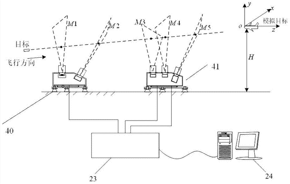
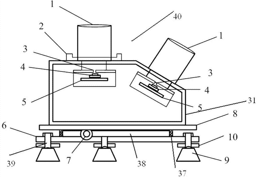
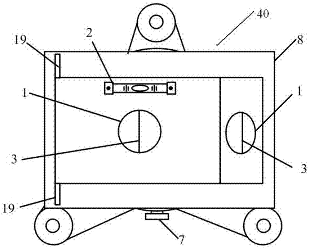
[0042] Such as figure 1 As shown, a large target surface miss-target correction test system is shown, which includes a first photoelectric detection target 40, a second photoelectric detection target 41, a timing and image acquisition instrument 23, wherein the first photoelectric detection target 40 and the second photoelectric detection target body 41 are adjacently arranged in the test section of the target track along the firing direction of the gun, and these two photoelectric detection target bodies are all connected with timing and image acquisition instrument 23, timing and image acquisition instrument 23 and A computer 24 is connected. Among them, the first photoelectric detection target body 40 and the second photoelectric detection target body 41 transmit the detection...


PUM


Abstract

The invention relates to a correction and test system for the miss distance of a large target surface. The correction and test system comprises a first photoelectric detection target, a second photoelectric detection target and a timing and image collecting instrument, wherein the first photoelectric detection target and the second photoelectric detection target are adjacently arranged on a test segment of a ballistic range in the direction of gun firing, the two photoelectric detection targets are respectively connected with the timing and image collecting instrument, and the timing and image collecting instrument is connected with a computer. Five intersection awning space geometry arrays produced by the two photoelectric detection targets are utilized for achieving measurement of target speeds, flight angle vectors and coordinates.

Description

technical field [0001] The present invention relates to a test system, specifically, the present invention relates to a high-altitude large target surface miss-measurement test system and a corresponding test method. Background technique [0002] In the shooting range test, the flight speed of the projectile and the test of this coordinate are the core parameters of weapon verification, especially the measurement of the miss distance of the high-altitude projectile relative to the simulated target in the air. dimensional coordinates, which is an important parameter related to weapon verification and finalization. In general, the condition for the amount of misses at high altitude relative to the target near-explosion is usually that the distance between the center of the target and the height of the ground is greater than 20 meters. For the measurement of projectile coordinates and other parameters, light curtain target intersection test methods, sky curtain target intersect...

Claims


Application Information

Patent Timeline
Patent Type & Authority Applications(China)
IPC IPC(8): G01P3/68G01B11/26G01B11/00
Inventor 李翰山雷志勇高俊钗王泽民
Owner XIAN TECHNOLOGICAL UNIV
Why Eureka
Try Eureka