Switchable automotive coolant pump

A car cooling and pump wheel technology, applied in the control of coolant flow, engine cooling, pumps, etc., can solve the problems of high production cost and complicated actuation arrangement

Inactive Publication Date: 2014-04-30
PIERBURG PUMP TECH
View PDF6 Cites 4 Cited by
  • Summary
  • Abstract
  • Description
  • Claims
  • Application Information

AI Technical Summary

Problems solved by technology

This actuation arrangement is complex and expensive to produce and causes problems i

Method used


Image

  • Switchable automotive coolant pump
  • Switchable automotive coolant pump
  • Switchable automotive coolant pump

Examples


Embodiment Construction

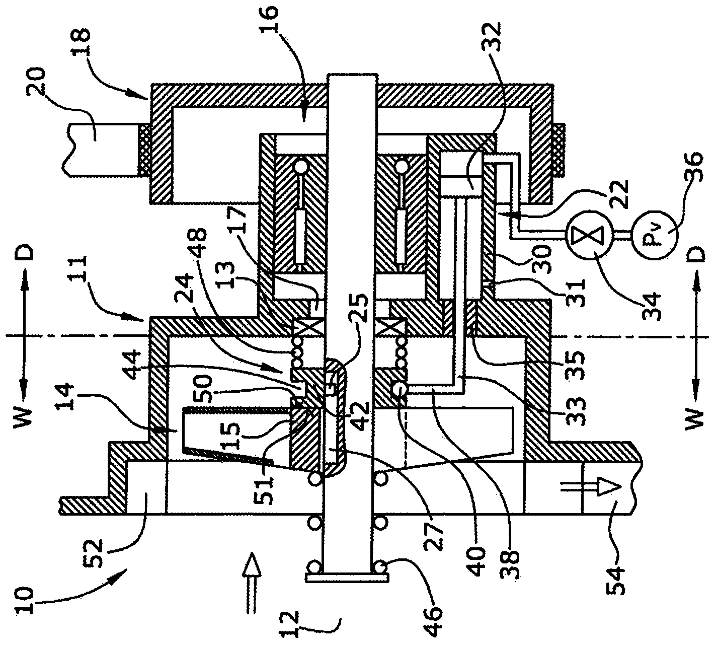
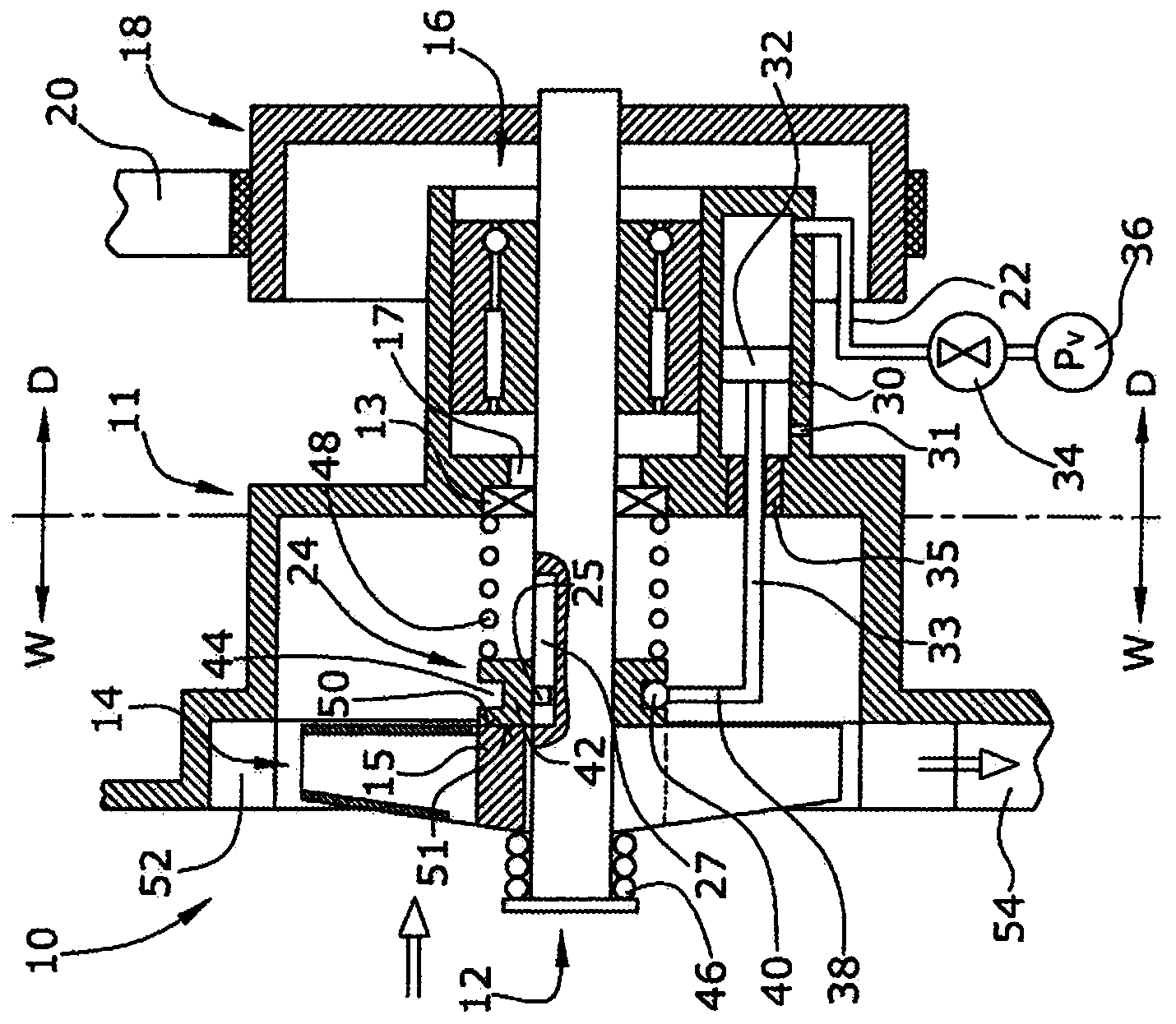
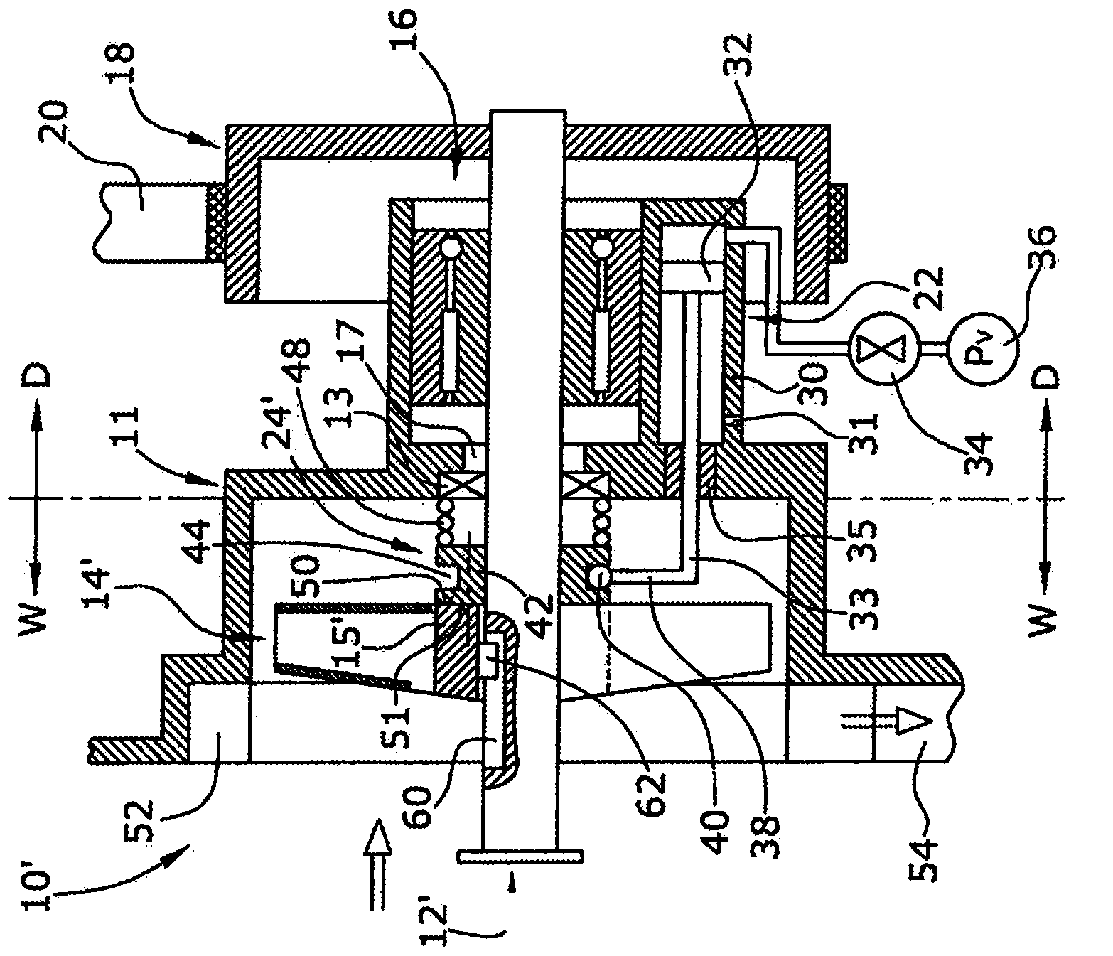
[0020] Figure 1 to 4 A switchable automobile coolant pump 10; 10' is shown, which is used to pump coolant, such as water, in a coolant circuit for cooling an internal combustion engine (not shown). The coolant pump 10; 10' is adapted to be mounted to the engine and is adapted to be driven by the engine via a transmission belt 20, which drives the pulley 18 of the coolant pump so that the pulley 18 of the coolant pump 10; 10' is always proportional to the engine speed The speed of rotation.

[0021] The coolant pump 10; 10' is provided with a housing 11 which separates the wet section W from the dry section D. The housing 11 supports the bearing 16 in the dry section D. The bearing 16 thus supports the rotatable rotor shaft 12; 12'. The pulley 18 is fixed to the rotor shaft 12 as a whole. The rotor shaft 12 protrudes through the opening 17 of the housing 11, in which an annular shaft seal 13 is provided to seal the annular gap between the opening edge of the opening 17 and th...


PUM


Abstract

The invention refers to a switchable automotive coolant pump (10; 10') with a pulley wheel (18) fixedly supported by a rotor shaft (12; 12'), a shaft sealing (13) separating the a dry section (D) from a wet section (W) with respect to the rotor shaft (12; 12), a pump wheel (14; 14') which is supported in the wet section (W) by the rotor shaft (12; 12') and which is arranged axially slidable between a pumping position and a non-pumping position, a linear actuator rod (33) being arranged in parallel to and eccentrically with respect to the rotor shaft (12; 12'), a rod sealing (35) separating the wet section and the dry section of the actuator rod (33), the actuator rod (33) being actuated by an actuator (22) arranged in the dry pump section (D), and a shift ring (24; 24') being arranged axially shiftable and rotatably fixed at the rotor shaft (12; 12') in the wet pump section (W), whereby the shift ring (24; 24') is axially moved by the actuator rod (33) and is axially moving the pump wheel (14).

Description

Technical field [0001] The invention relates to a switchable mechanical automobile coolant pump for pumping coolant, which is used for cooling an internal combustion engine. Background technique [0002] The mechanical coolant pump is directly driven by the internal combustion engine, for example via a belt driving the pulley of the coolant pump. If the pulley is directly connected to the pump wheel, the performance of the pump depends on the speed of the internal combustion engine. To allow more responsive control of the coolant pump, the mechanical coolant pump may be provided with a friction clutch to connect the pulley to the rotor shaft only as needed. The friction clutch is usually arranged in the dry section of the coolant pump. [0003] DE102006039680A1 discloses a switchable mechanical automotive coolant pump in which the pump wheel can move axially between a pumping position and a non-pumping position. The pump wheel is actuated by an actuator rod that is concentric wi...

Claims


Application Information

Patent Timeline
IPC IPC(8): F01P5/12F01P7/16F16D25/08F04D15/00
CPCF01P7/162F01P5/12F04D15/0027F04D29/042F04D13/022
Inventor J-M.杜兰德
Owner PIERBURG PUMP TECH
Why Eureka
Try Eureka