Single-axis actuator

An actuator, single-axis technology, used in the direction of shafts, bearings, shafts and bearings

Active Publication Date: 2014-04-30
NSK LTD
View PDF6 Cites 3 Cited by
  • Summary
  • Abstract
  • Description
  • Claims
  • Application Information

AI Technical Summary

Problems solved by technology

In addition, in the conventional uniaxial actuator, the area of ​​the outer circumference of the screw shaft is less than

Method used


Image

  • Single-axis actuator
  • Single-axis actuator
  • Single-axis actuator

Examples


no. 1 Embodiment approach ]

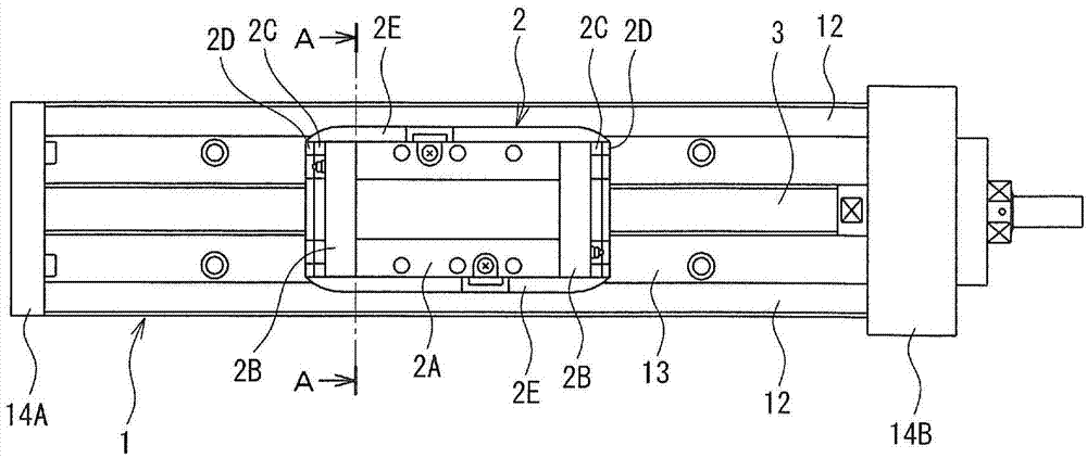
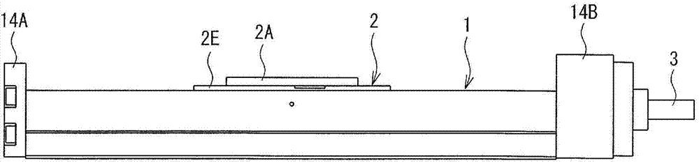
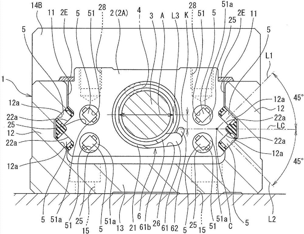
[0067] Figure 1~3 It is a plan view, a side view, and a cross-sectional view (along figure 1 A cross-sectional view of line A-A in).

[0068] Such as Figure 1~3 As shown, the uniaxial actuator includes: a guide rail 1 , a sliding body 2 , a screw shaft 3 , a ball 4 , a roller 5 , and an end reverser 6 .

[0069] The cross section of the guide rail 1 perpendicular to the longitudinal direction is U-shaped, and the slider 2 is housed in the U-shaped concave portion 11 . The guide rail 1 is composed of a bottom portion 13 , end members 14A, 14B, and a pair of side portions 12 , and the inner surfaces of the side portions 12 face the respective side surfaces of the slider 2 . On the inner surface of each side portion 12, a rolling surface 12a constituting a rolling passage of the roller 5 is formed. Through-holes 15 for inserting mounting bolts are formed in the bottom portion 13 of the guide rail 1 . The through hole 15 is formed at a position bordering each side part 12 o...

no. 2 Embodiment approach ]

[0089] exist Figure 7 The uniaxial actuator of the second embodiment shown is the same as the uniaxial actuator of the first embodiment except that the rolling elements of the linear guide mechanism are different.

[0090] In the second embodiment, since the balls 7 are provided as rolling elements, the rolling grooves (rolling surfaces) 12b of the balls 7 are formed on the inner surface of the side portion 12 of the guide rail 1, and the rolling grooves (rolling surfaces) are formed on the slider main body 2A. 22b. Further, a through-hole 29 extending in the longitudinal direction of the screw shaft is formed in the slider main body 2A as a return path for the ball 7 .

[0091] Thus, the linear guide mechanism of the uniaxial actuator is constituted by the rolling groove 12b of the guide rail 1, the rolling groove 22b of the slider body 2A, the ball 7, the return passage 29 of the slider body 2A, and the direction switching passage of the end cover 2B. . In addition to th...

no. 3 Embodiment approach ]

[0094] The uniaxial actuator of the third embodiment is the same as the uniaxial actuator of the first embodiment except that the structure of the slider is different.

[0095] Figure 8 A front view showing the slider main body constituting the uniaxial actuator of this embodiment is shown in Figure 9 Rear view is shown in . which is, Figure 8 is a diagram showing one end surface of the slider main body in the longitudinal direction of the screw shaft, Figure 9 It is a diagram showing the other end surface in the longitudinal direction of the screw shaft. Figure 10 is a diagram showing a cross-section of one end of the slider body in the longitudinal direction of the screw shaft, and corresponds to the Figure 8 A cross-sectional view of line A-A in. Figure 11 is a diagram showing the cross-section of the other end of the slider body in the longitudinal direction of the screw shaft, which corresponds to the Figure 9 A cross-sectional view of line A-A in.

[0096]...


PUM


Abstract

The present invention addresses the problem of reducing the size of the cross-sectional shape perpendicular to the lengthwise direction of the threaded shaft of a slider when the diameter of the outer peripheral circle of a threaded shaft is the same as that of a single-axis actuator which uses a circulation tube to form the ball return path of the single-axis actuator, and of increasing the load capacity when the dimensions in the lengthwise direction of the threaded shaft of the slider are the same. With the present invention a ball return path, which returns the balls (4) of a ball screw mechanism from the terminal point to the starting point of a raceway, is formed by means of a through-hole (24) that penetrates in the lengthwise direction of a threaded shaft (3) of a slider (2), and by means of an end deflector (6). The end deflector (6) has a direction-switching path connecting with the through-hole (24). The main body (61) of the end deflector (6) is mated with notch parts (26) formed at both ends in the lengthwise direction of the threaded shaft (3) of the slider main body (2A).

Description

technical field [0001] The invention relates to single axis actuators. Background technique [0002] A uniaxial actuator composed of a ball screw mechanism and a linear guide mechanism has: a guide rail whose cross-section perpendicular to the longitudinal direction is U-shaped; a sliding body disposed in a U-shaped concave portion of the guide rail; and A plurality of rolling bodies are arranged between the guide rail and the sliding body. A nut is formed in the slide body parallel to the guide rail, and a plurality of balls are arranged on a track formed by a helical groove of the nut and a helical groove of a screw shaft penetrating the nut. [0003] The guide rail has a rolling surface constituting a rolling passage of the rolling element on each inner surface facing each side surface of the sliding body. The sliding body has: a rolling surface that faces the rolling surface of the guide rail to form a rolling passage; a return passage of the rolling element; and a dir...

Claims


Application Information

Patent Timeline
IPC IPC(8): F16H25/22F16C29/06
CPCF16C29/0633F16H2025/204F16H2025/2034F16H25/2219F16C29/0611F16C29/0609F16C29/063F16C2322/39Y10T74/18576F16H25/2214
Inventor 下村裕哉
Owner NSK LTD
Why Eureka
Try Eureka