Tapping machine automatic feeding system

An automatic feeding and tapping machine technology, which is applied in the direction of metal processing machinery parts, measuring/indicating equipment, tangential feeding devices, etc., can solve the problem that it is difficult to guarantee the stability of pipe fittings and the consistency of their state, which affects working stability and Reliability, work efficiency is difficult to continue to improve and other problems, to achieve the effect of overcoming unstable work, good consistency, and convenient operation

Inactive Publication Date: 2014-05-07
HEBEI JIANZHI CASTING GROUP
View PDF8 Cites 2 Cited by
  • Summary
  • Abstract
  • Description
  • Claims
  • Application Information

AI Technical Summary

Problems solved by technology

But this invention still has some defects: 1. Due to the influence of the shape and position of the silo, it is still inconvenient to install the clamps; 2. Since the pipe fittings entering the fixture seat from the silo are freely falling through the gravity of the pipe itself, the pipe fittings are in the process of moving and moving. It is difficult to guarantee the stability and consistency of the state during the connection process, which will affect the stability and reliability of subsequent work; ③ It is difficult to continue to improve work efficiency

Method used


Image

  • Tapping machine automatic feeding system
  • Tapping machine automatic feeding system
  • Tapping machine automatic feeding system

Examples


Embodiment Construction

[0018] The present invention will be described in detail below in conjunction with the accompanying drawings.

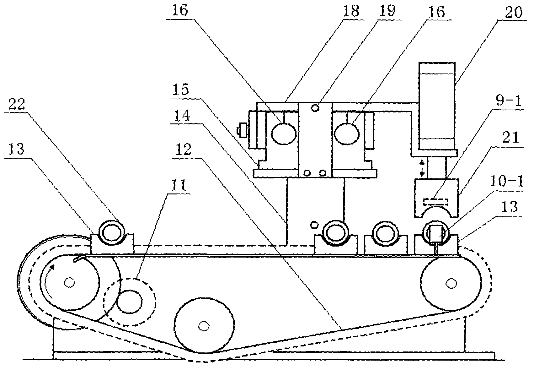
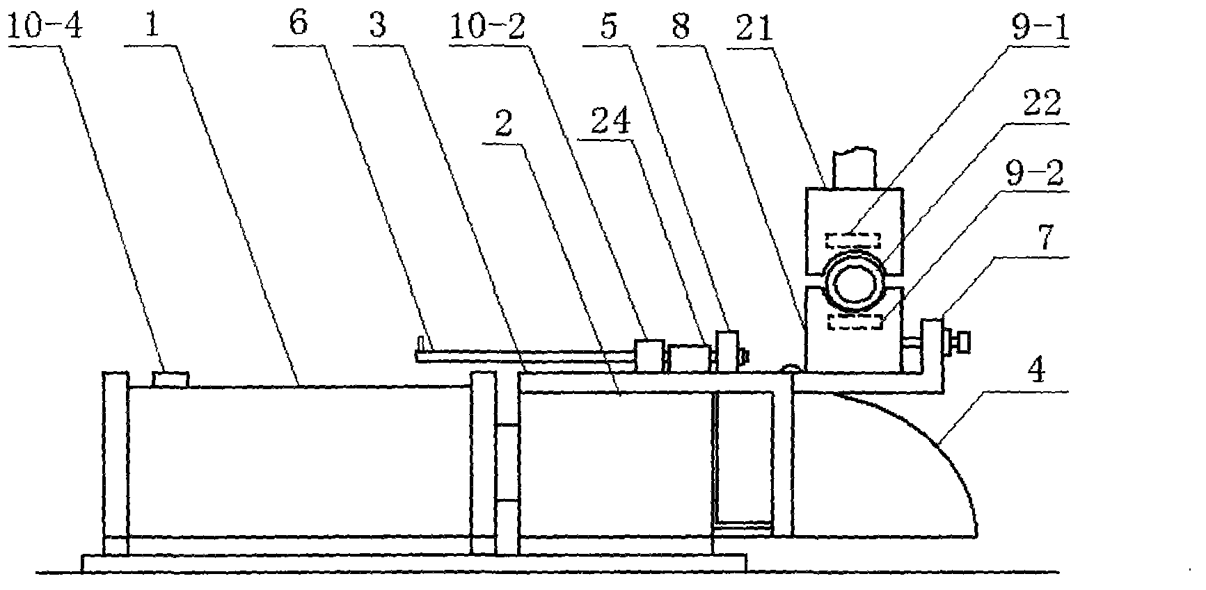
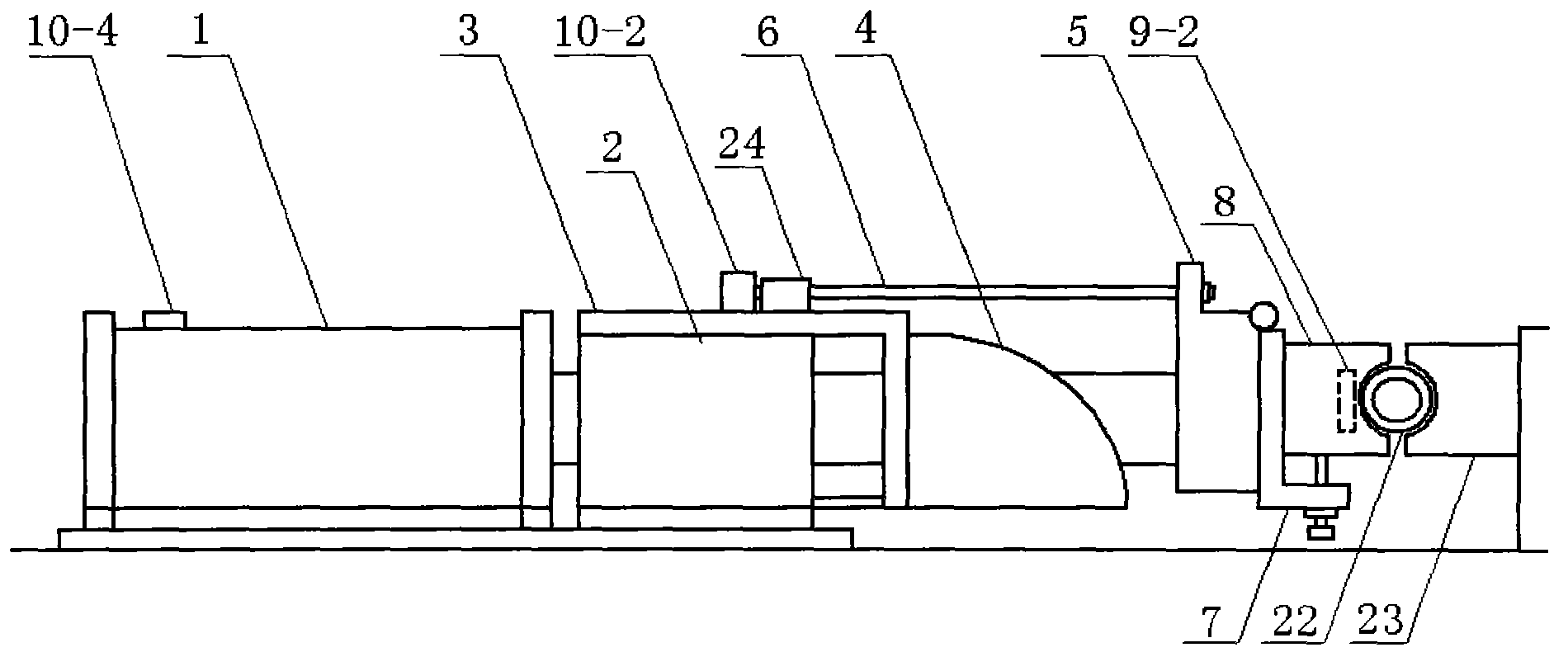
[0019] Such as Figure 1-4 As shown, the present invention includes a feeding cylinder 1, a guide seat 2, a support 3, an overturning slideway 4, a connecting plate 5, a guide rod 6, a fixture seat 7, a movable fixture 8, The feeding mechanism and detection switches 10-1, 10-2, 10-3, 10-4 formed by electromagnet 9-2 also include a low-speed motor 11, a chain 12, and a material holder arranged on one side of the manual clamping station. 13, and the supporting plate 14, guide column frame 15, guide column 16, material transfer cylinder 17, linear bearing body 18, limit screw 19, and material suction cylinder are arranged above the middle of the manual loading station. 20, the material-shifting mechanism that suction chuck 21, electromagnet 9-1 form.

[0020] Such as figure 1 , 2 , 4, before starting the machine, the linear bearing body 18 is at one end of the guide...


PUM


Abstract

The invention discloses a tapping machine automatic feeding system matched with a metal pipe fitting tapping machine. The tapping machine automatic feeding system comprises a feeding mechanism and a detecting switch, wherein the feeding mechanism is arranged in the middle of a manual clamping station and formed by a feeding cylinder, a guide seat, a support, an overturning slideway, a connecting plate, a guide rod, a clamp seat, a movable clamp and an electromagnet. The tapping machine automatic feeding system further comprises a material conveying mechanism and a material moving mechanism, wherein the material conveying mechanism is arranged on one side of the manual clamping station and formed by a low-speed motor, a chain and a material support; and the material moving mechanism is arranged above the middle of the manual clamping station and formed by a supporting plate, a guide pillar frame, a guide pillar, a material moving cylinder, a linear bearing body, a limiting screw, a material absorbing cylinder, a material absorbing clamping head and an electromagnet. First the material conveying mechanism is charge of conveying pipe fittings to be in place, the material moving mechanism moves the sent pipe fittings to the feeding mechanism, and the feeding mechanism sends the pipe fittings to a processing station to perform tapping operation. The tapping machine automatic feeding system has the advantages of working stably and reliably and being good in consistency, convenient to operate and high in working efficiency.

Description

technical field [0001] The invention relates to an automatic feeding system for a tapping machine, in particular to an automatic feeding system for a tapping machine matched with a metal pipe fitting tapping machine, which belongs to the technical field of mechanical processing equipment. Background technique [0002] The internal thread of metal pipe fittings needs to be processed by tapping machine. When the tapping machine is processing the internal thread of metal pipe fittings, the operator first installs the pipe fittings to be tapped on the movable fixture one by one (that is, manual clamping), and then starts the cylinder to push the movable fixture with the pipe fittings to the processing At the station, make the movable jig coincide with the fixed jig to clamp the pipe fittings, start the tapping machine to start tapping in the forward direction and reverse the taper, and then take out the processed pipe fittings from the jig. This kind of processing method of man...

Claims


Application Information

Patent Timeline
IPC IPC(8): B23G11/00B23Q17/00
Inventor 任劲峰李铁良杨翠利李益春任福艳
Owner HEBEI JIANZHI CASTING GROUP
Why Eureka
Try Eureka