
The loading and unloading device and application of the groove grinding machine for the outer ring of the automobile hub bearing unit

A technology for automobile wheels and bearings, applied in the direction of grinding machines, grinding feed movement, grinding/polishing equipment, etc., can solve the problems that the grinding speed cannot be significantly increased, the processing cycle of the workpiece is prolonged, and the loading and unloading time is reduced. The effect of non-processing time, less mechanical action, and fast loading and unloading speed

Active Publication Date: 2016-09-07
PUYANG BEAIN CNC MACHINERY & EQUIP
View PDF6 Cites 0 Cited by
  • Summary
  • Abstract
  • Description
  • Claims
  • Application Information

AI Technical Summary

Problems solved by technology

[0002]At present, the loading and unloading time of the third-generation automobile wheel bearing grinding machine is longer, which prolongs the processing cycle of the workpiece. In the environment where the grinding speed cannot be significantly increased, it can only reduce the Processing time to improve efficiency, especially loading and unloading time urgently needs to be reduced

Method used


Image

  • The loading and unloading device and application of the groove grinding machine for the outer ring of the automobile hub bearing unit
  • The loading and unloading device and application of the groove grinding machine for the outer ring of the automobile hub bearing unit
  • The loading and unloading device and application of the groove grinding machine for the outer ring of the automobile hub bearing unit

Examples


Embodiment Construction

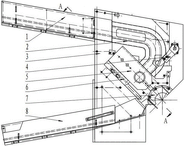
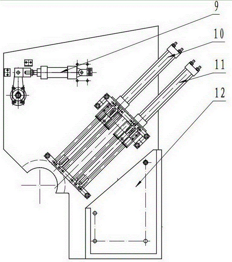
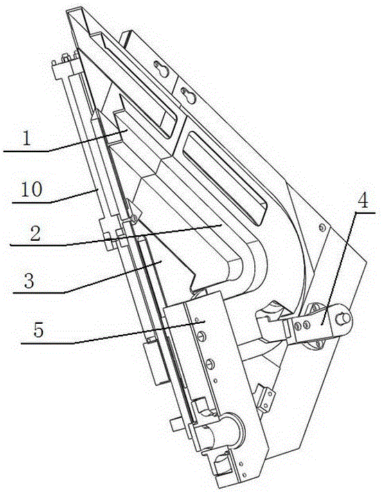
[0017] like figure 1 As shown, the loading and unloading device for the groove grinding of the outer ring of the automobile hub bearing unit includes a panel, and the panel is fixed on the panel support. The panel is fixedly equipped with an upper material passage, a transitional material passage, an unloading passage, a distribution oil cylinder, a main manipulator oil cylinder, an auxiliary manipulator oil cylinder, and an unloading passage. The cross-section of the feeding channel is in an inverted "T" shape. The transition channel is arc-shaped, and the cross-section is inverted "T" shape. The upper feed channel is connected with the transition feed channel. A material distributing manipulator is arranged on one side of the transition material channel, and the material distributing manipulator is connected with the material distributing oil cylinder. The main manipulator and the auxiliary manipulator are located at the end of the transition material channel. The main m...


PUM


Abstract

The invention relates to a bearing grinder charging and discharging technology, in particular to a charging and discharging device for an outer circle groove grinder of an automobile hub bearing unit, and the application of the device. The charging and discharging device for the outer circle groove grinder of the automobile hub bearing unit comprises a panel, wherein a charging channel, a transitional material channel, a discharging channel, a material separation oil cylinder, a main manipulator oil cylinder and an auxiliary manipulator oil cylinder are fixedly arranged on the panel; the charging channel is connected with the transitional material channel; a material separation manipulator is arranged on one side of the transitional material channel and is connected with the material separation oil cylinder; the main manipulator oil cylinder and the auxiliary manipulator oil cylinder are positioned at the tail end of the transitional material channel; a main manipulator is connected with the main manipulator oil cylinder; an auxiliary manipulator is connected with the auxiliary manipulator oil cylinder; a fan-shaped plate is arranged at a grinding station on the panel; the discharging channel is arranged at a position corresponding to the fan-shaped plate. Compared with a common charging and discharging device, the charging and discharging device for the outer circle groove grinder of the automobile hub bearing unit has the advantages that waiting time for discharging and charging is not needed; the device is less in mechanical motion, high in charging and discharging speed and high in stability, the non-machining time is greatly shortened, and the efficiency is improved.

Description

Technical field: [0001] The invention relates to a bearing grinding machine loading and unloading technology, in particular to an automotive wheel hub bearing unit outer ring channel grinding machine loading and unloading device and the application of the device. Background technique: [0002] At present, the loading and unloading time of the third-generation automobile wheel bearing grinding machine is long, which prolongs the processing cycle of the workpiece. In the environment where the grinding speed cannot be significantly improved, the only way to improve efficiency is to reduce the non-processing time, especially the urgent need to reduce the loading and unloading time. Invention content: [0003] The object of the present invention is to provide a reliable and fast loading and unloading device and the application of the device, which solves the deficiencies of the prior art. [0004] The technical scheme provided by the invention is: [0005] The loading and unlo...

Claims


Application Information

Patent Timeline
Patent Type & Authority Patents(China)
IPC IPC(8): B24B19/06
CPCB24B41/005
Inventor 张振林王玉峰张建道
Owner PUYANG BEAIN CNC MACHINERY & EQUIP
Learn More