Emergency braking device of elevator

An emergency braking and elevator technology, applied in transportation, packaging, elevators, etc., can solve the problems of loss of shock absorption, inability to exert elastic characteristics, lack of reproducibility of buffer body, etc., and achieve the effect of restraining height, reducing depth and convenient construction

Inactive Publication Date: 2014-05-07
HITACHI LTD
View PDF6 Cites 8 Cited by
  • Summary
  • Abstract
  • Description
  • Claims
  • Application Information

AI Technical Summary

Problems solved by technology

[0014] According to the above-mentioned Patent Document 1, although the impact force at the time of collision can be suppressed, since the elasticity and deformation of the cushion body change due to temperature, humidity, aging, etc., the cushion body lacks reproducibility.
At this time, since the distance between the upper surface of the brake piece and the top plate of the main body of the emergency brake device will also change, it is difficult to correctly position the brake piece at the specified height position with a small error. The problem that the braking device cannot obtain a stable braking force
[0015] When using an elastic body such as rubber as a buffer body, the buffer body may be hydrolyzed due to moisture absorption. At this time, since the elastic properties cannot be exerted at all, the function of absorbing shock may be lost. As a result, as in the prior art, there are Problems where the prescribed braking force cannot be obtained

Method used


Image

  • Emergency braking device of elevator
  • Emergency braking device of elevator
  • Emergency braking device of elevator

Examples


no. 1 example

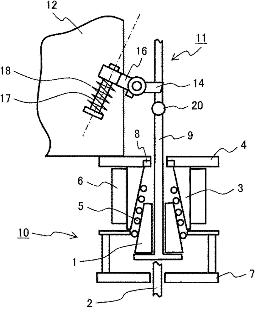
[0065] figure 1 is a schematic diagram of the emergency braking device according to the first embodiment of the present invention. The emergency braking device 10 is configured to have a left-right symmetrical structure with respect to the guide rail 2 . The pair of stoppers 1 are arranged substantially parallel to the guide rail 2 so as to clamp the guide rail 2 , and there is a slight gap between the pair of stoppers 1 and the guide rail 2 . The back surface of the braking member 1 is a smooth inclined surface in the shape of a wedge that narrows at the top.

[0066] The back of the stopper 1 is provided with a guide member 3 . The inner side of the guide member 3 forms an inclined surface parallel to the inclined surface of the brake piece 1, and the outer side forms a vertical surface. , This vertical surface is clamped by the brake spring 6 . A roller 5 for guiding the movement of the brake piece 1 is provided between the brake piece 1 and the guide member 3. 4 denot...

no. 2 example

[0094] Figure 7 It is a schematic diagram of the emergency braking device concerning the 2nd Embodiment of this invention. The difference from the first embodiment described above lies in the holding mechanism 36 of the lifting member 31 . Therefore, repeated description of the stopper portion A of the clamping rail is omitted here.

[0095] A cylindrical locking portion 32 extending in the horizontal direction is attached to the lifting member 31 . On the other hand, various members for holding the locking portion 32 are provided on the elevator car 45 . Specifically, a rotation link 33 and a fixed link that are rotatable around a rotation shaft 34 are provided. An engaging portion 46 is provided below the base end portion of the rotation link 33 to prevent the rotation link 33 from moving clockwise from the illustrated position.

[0096] Conversely, when an upward force acts on the rotation link 33 , only the rotation link 33 rotates around the rotation axis. The fixed...

no. 3 example

[0109] Figure 10 It is a schematic diagram of the emergency braking device concerning the 3rd embodiment of this invention.

[0110] exist Figure 10 Among them, the holding mechanism 55 is composed of the drive mechanism 47 , the electromagnetic actuator 50 , the drive circuit 51 and the control circuit 52 .

[0111] In order to hold the locking portion 49 of the lifting member 48, a driving mechanism 47 having an electromagnetic actuator 50 movable in the horizontal direction is provided on the elevator car. The drive mechanism 47 is driven by the control circuit 52 and the drive circuit 51 . When the lifting member 48 is lifted to activate the emergency braking device, the drive mechanism 47 is energized to pull the electromagnetic actuator 50 in the direction shown by arrow 1. After the lifting action is completed, the power supply is cut off to activate the electromagnetic actuator 50. Return to the original position. The same is true at the time of resetting. The el...


PUM


Abstract

The invention provides an emergency braking device of an elevator. The device restrains position variation of brake components in a braking initial period and generates stable braking forces, so as to effectively stop the elevator by a specified deceleration. In the elevator with the emergency braking device, in order to stop the elevator car, the emergency braking device makes the brake components slidably press guiding rails in an elevating channel, so as to generate braking forces. The elevator is provided with a maintaining mechanism. The maintaining mechanism maintains a lifting component on the elevator car when the brake components are lifted, and when the brake components are reset, the lifting component of the brake components is separated from the elevator car through lifting operation of the elevator car.

Description

technical field [0001] The invention relates to an emergency braking device of an elevator, in particular to an emergency braking device capable of generating stable braking force in a high-speed elevator. Background technique [0002] As the prior art, an emergency braking device is provided in the elevator as a safety device. When the elevator car descends beyond a certain speed limit, the emergency braking device stops the elevator car from descending with an appropriate deceleration. [0003] When the elevator car reaches a speed above the specified descending speed, the emergency braking device lifts the brake member with two wedge-shaped friction materials in the brake spring, and uses the restoring force generated by the elastic deformation of the brake spring to The braking force is generated by pressing the guide rails arranged in the lifting channel. The braking parts are usually made of cast iron, copper sintered alloy or ceramics with moderate friction coefficien...

Claims


Application Information

Patent Timeline
Patent Type & Authority Applications(China)
IPC IPC(8): B66B5/16
Inventor 佐藤五郎礒谷仁平野薰座间秀隆远藤广基
Owner HITACHI LTD
Why Eureka
Try Eureka