Eureka AIR delivers breakthrough ideas for toughest innovation challenges, trusted by R&D personnel around the world.

Flour mill roller transmission mechanism and flour mill

A technology of transmission mechanism and pulverizer, which is applied in transmission devices, mechanical equipment, belts/chains/gears, etc., can solve the problems of small transmission force, difficult assembly, and difficult installation of toothed wedge belts, so as to prolong the service life, Avoid excessive stretching and improve stability

Active Publication Date: 2014-05-07
COFCO ENG EQUIP ZHANGJIAKOU
View PDF5 Cites 3 Cited by
  • Summary
  • Abstract
  • Description
  • Claims
  • Application Information

AI Technical Summary

Problems solved by technology

[0003] In addition, the outer tooth surface of the toothed V-belt used in existing equipment is usually an arc tooth with a pitch of 8mm or 14mm (national standard type). Through calculation and a large number of practices, it has been proved that the toothed V-belt with a pitch of 8mm is due to the gap between the belt and the gear teeth. The joint surface of the belt is small, and the transmission force is relatively small. Although the joint surface of the toothed V-belt with a pitch of 14mm is large, the wrap angle is small due to the excessive pitch; both the fast roller and the tension pulley have wedges. , it is more difficult to install the toothed V-belt, so there is a certain degree of difficulty in assembly

Method used


Image

  • Flour mill roller transmission mechanism and flour mill
  • Flour mill roller transmission mechanism and flour mill
  • Flour mill roller transmission mechanism and flour mill

Examples


Embodiment Construction

[0042] Specific embodiments of the present invention will be described in detail below in conjunction with the accompanying drawings. It should be understood that the specific embodiments described here are only used to illustrate and explain the present invention, and are not intended to limit the present invention.

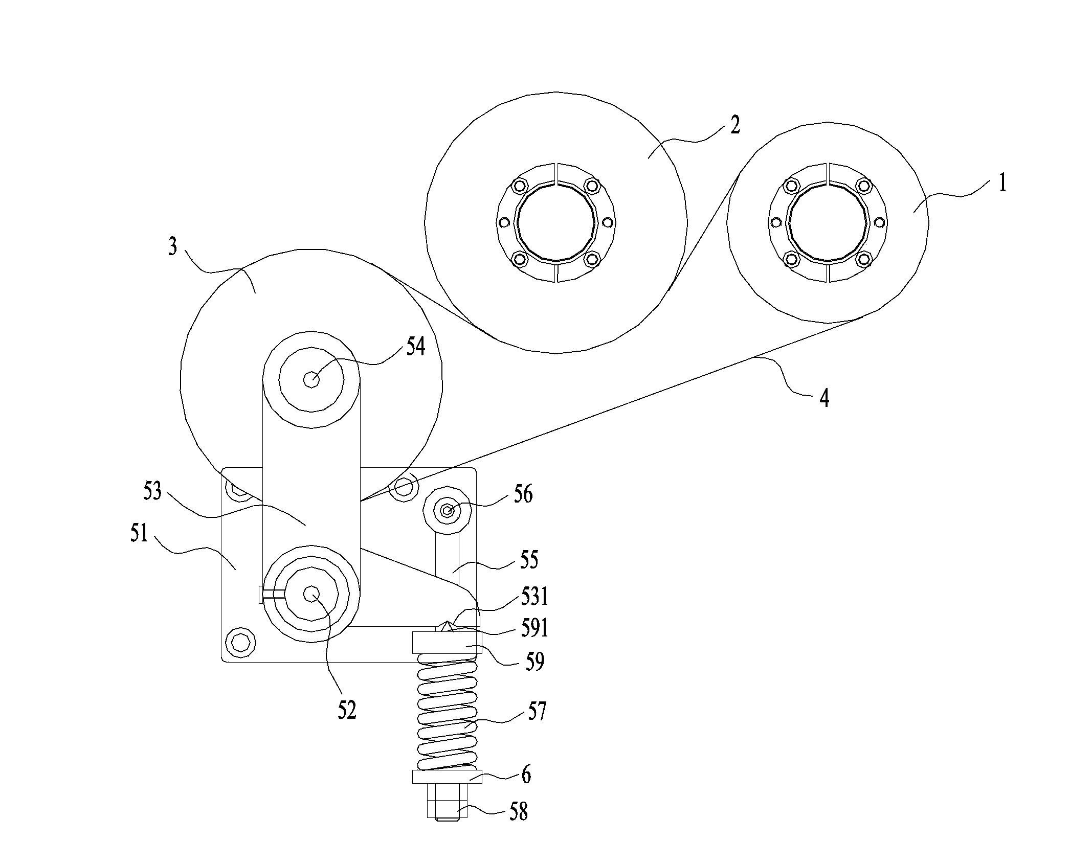
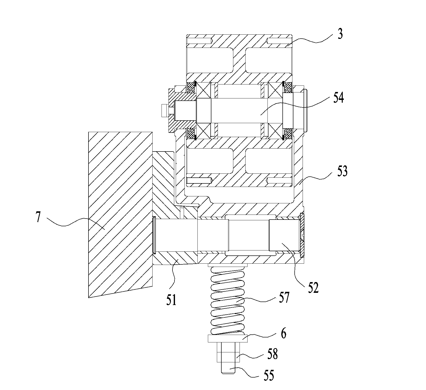
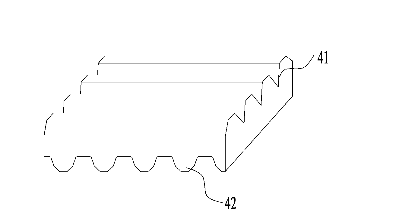
[0043] The mill roller transmission mechanism proposed by the present invention, such as figure 1 , figure 2 As shown, it includes frame 7, fast roller 1, slow roller 2 and toothed wedge belt 4. The outer peripheral surface of the wheel 1 is engaged, the outer tooth surface of the toothed wedge belt 4 is engaged with the outer peripheral surface of the slow roller 2, and the mill roller transmission mechanism also includes:

[0044] Tension seat 51, the tension seat 51 is fixed on the frame 7;

[0045] A support shaft 52, one end of the support shaft 52 is pivotally connected to the tension seat 51;

[0046] Swing frame 53, one side of this swing frame 53 i...


PUM


Abstract

The invention discloses a flour mill roller transmission mechanism which comprises a rack (7), a quick roller (1), a slow roller (2) and a ribbed belt (4). The ribbed belt (4) is provided with an inner tooth face and an outer tooth face, the inner tooth face of the ribbed belt (4) is connected with the peripheral surface of the quick roller (1), the outer tooth face of the ribbed belt (4) is connected with the peripheral surface of the slow roller (2), and the flour mill roller transmission mechanism further comprises a tensioning seat (51), a supporting shaft (52), a swing frame (53), a rolling shaft (54), a tensioning wheel (3) and a pressing mechanism. A tensioning mechanism is arranged to be of an elastic adjustable structure, a buffering space exists when the tensioning wheel is connected with the inner tooth wall of the ribbed belt, and the tension of the ribbed belt can be buffered through the elastic force of the tensioning mechanism. The driving force and stability are improved by improving the pith of tooth bodies of the ribbed belt, and the ribbed belt is made to be easy and convenient to mount by improving the peripheral surface of the tensioning wheel. The invention further discloses a four mill with the flour mill roller transmission mechanism.

Description

technical field [0001] The invention relates to the field of milling equipment, in particular to a mill roller transmission mechanism and a mill. Background technique [0002] In the prior art, the pulverizer usually adopts a three-roller transmission structure. The three rollers include a fast roller with wedges, a slow roller with teeth, and a tensioning pulley with wedges. The transmission mode is to use toothed wedges Belt transmission, but the tensioning mechanism in the three-roller transmission usually adopts eccentric rigid tensioning. The specific structure is that the tensioning wheel is directly installed on the eccentric shaft, and the tensioning wheel is slightly shifted by rotating the eccentric shaft, forcing the toothed wedge belt Be tensed. This structure has certain disadvantages. For example, when the pulverizer is started, or when hard debris is mixed on the joint surface between the toothed belt 4 and the roller, the tension of the toothed belt will inc...

Claims


Application Information

Patent Timeline
Patent Type & Authority Applications(China)
IPC IPC(8): F16H7/08B02C23/00
CPCB02C23/00F16G5/20F16H7/08F16H2007/0806
Inventor 徐桂清魏所明
Owner COFCO ENG EQUIP ZHANGJIAKOU
Why Eureka
Eureka Blog
Learn More