Anchorage damage test device and test method for fracture surrounding rock
A technology of anchorage performance and test method, which is applied in the direction of measuring device, preparation of test samples, and testing material strength by applying stable tension/pressure, etc. Changes and other problems to achieve the effect of preventing transitional stretching and volume deformation
- Summary
- Abstract
- Description
- Claims
- Application Information
AI Technical Summary
Problems solved by technology
Method used
Image
Examples
Embodiment 1
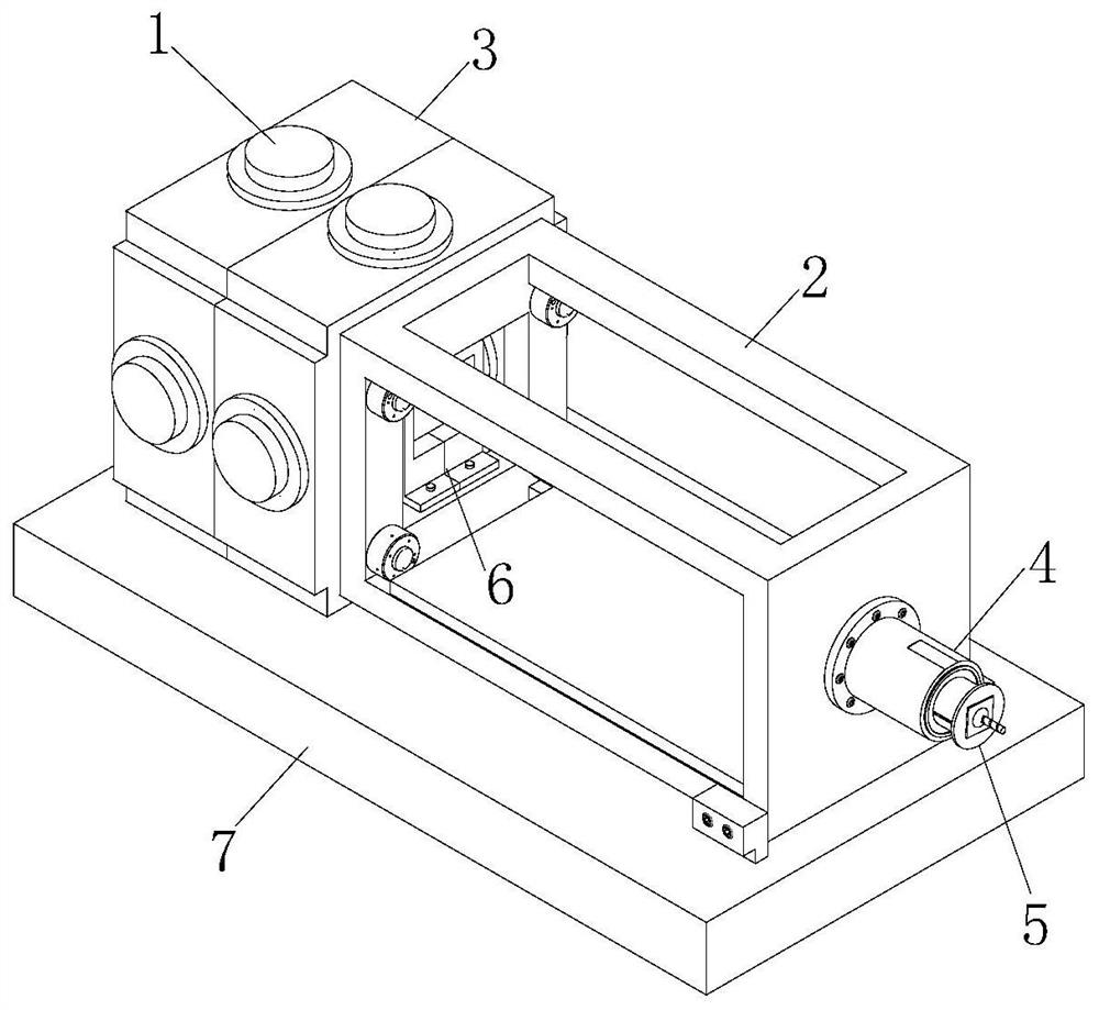
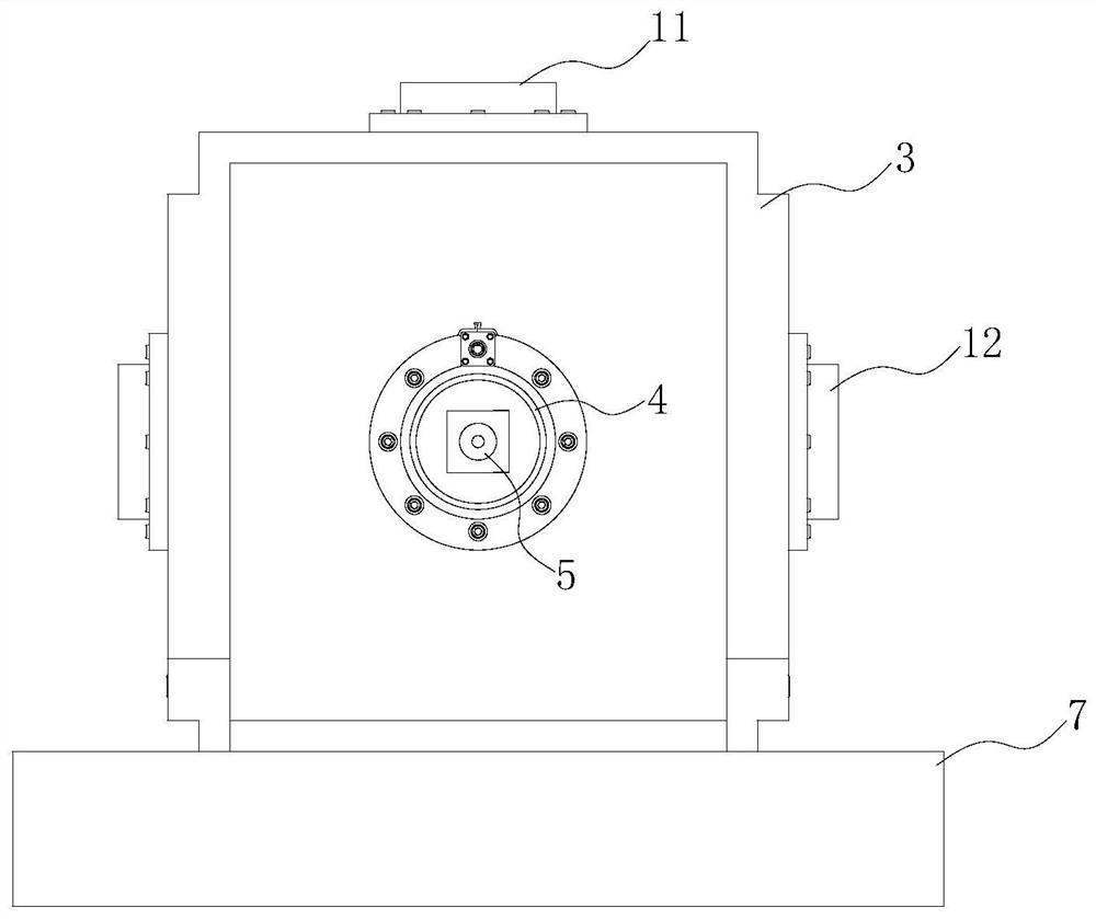
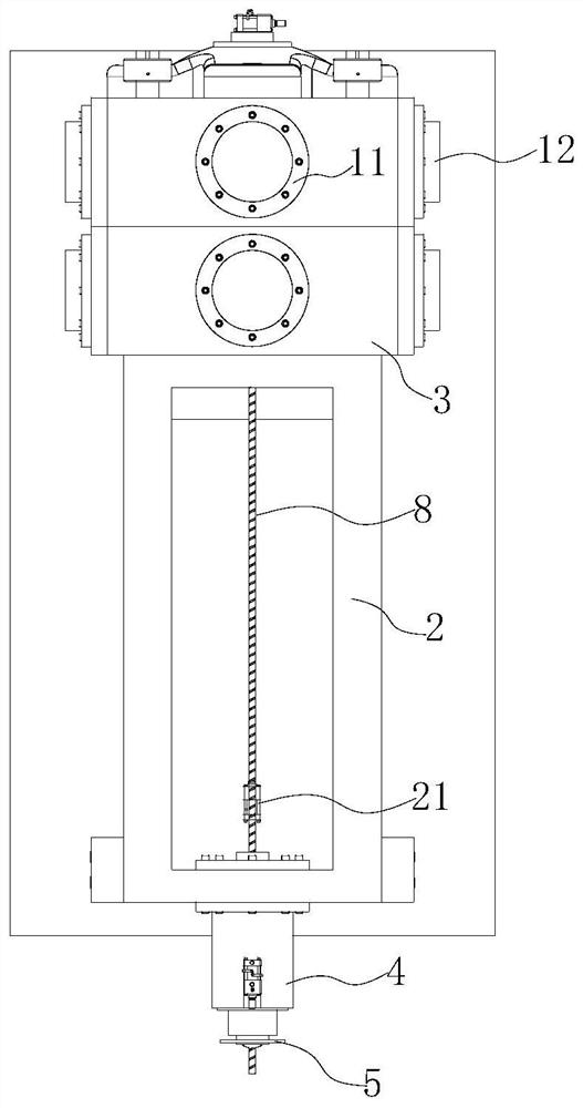
[0055] like Figure 1 to Figure 3 As shown in the figure, the structure of the fracture surrounding rock anchorage damage test device specifically includes a servo hydraulic cylinder 1 , a connecting frame 2 , a loading frame 3 , an annular oil cylinder 4 and an anchor rod fixing fixture 5 . The damaged crack specimen 9 is loaded by the servo hydraulic cylinder 1 and the loading frame 3, thereby simulating the in-situ stress conditions of the anchoring section; the annular oil cylinder 4 is used for loading, so as to simulate the stress on the bolt along the direction of the bolt, and then through the device It can carry out pull-out test of anchoring section under different damage and fissure conditions, common pull-out test of anchor rod, pull-out test of non-damaged anchor section of anchor rod, etc., which provides a foundation for indoor test of anchor rod and research on anchoring performance of anchor rod.
[0056] The servo hydraulic cylinder 1 is fixed on the loading ...
Embodiment 2
[0067] like Figure 1 to Figure 3 As shown in the figure, a fracture surrounding rock anchorage damage testing device, its structure specifically includes a servo hydraulic cylinder 1, a connecting frame 2, a loading frame 3, an annular oil cylinder 4 and an anchor rod fixing fixture 5. Among them, such as Figure 4As shown, the servo hydraulic cylinder 1 is fixed on the loading frame 3, the servo hydraulic cylinder 1 includes an upper servo hydraulic cylinder 11, a rear servo hydraulic cylinder 13 and a side servo hydraulic cylinder 12, and the upper servo hydraulic cylinder 11 is arranged on the top of the loading frame 3 towards the For lower loading, the side servo hydraulic cylinders 12 are correspondingly arranged on both sides of the upper servo hydraulic cylinder 11, and the corresponding set of servo hydraulic cylinders have the same loading range. The rear servo hydraulic cylinder 13 can be loaded along the setting direction of the test bolt 8, so as to simulate the...
Embodiment 3
[0079] like Figure 1 to Figure 3 As shown in the figure, a fracture surrounding rock anchorage damage test device, the structure of which specifically includes a servo hydraulic cylinder 1, a connecting frame 2, a loading frame 3, an annular oil cylinder 4 and an anchor rod fixing fixture 5. The servo hydraulic cylinder 1 is fixed on the loading frame 3. The servo hydraulic cylinder 1 includes an upper servo hydraulic cylinder 11 and a side servo hydraulic cylinder 12. The upper servo hydraulic cylinder 11 is arranged on the top of the loading frame 3 to load downward, and the side servo hydraulic cylinder 12 corresponds to They are arranged on both sides of the upper servo hydraulic cylinder 11, and the corresponding set of servo hydraulic cylinders have the same loading range. There are at least two upper servo hydraulic cylinders 11, which independently load the damaged fracture specimen. Two corresponding side servo hydraulic cylinders 12 are respectively provided on both...
PUM
 Abstract
Description
Claims
Application Information
 - R&D
- Intellectual Property
- Life Sciences
- Materials
- Tech Scout
- Unparalleled Data Quality
- Higher Quality Content
- 60% Fewer Hallucinations
Browse by: Latest US Patents, China's latest patents, Technical Efficacy Thesaurus, Application Domain, Technology Topic, Popular Technical Reports.
© 2025 PatSnap. All rights reserved.Legal|Privacy policy|Modern Slavery Act Transparency Statement|Sitemap|About US| Contact US: help@patsnap.com


