
Variable displacement rotor oil pump

A rotor oil pump, variable technology, applied in lubricating pumps, mechanical equipment, engine components, etc., can solve the problems of high operating noise and low oil pump efficiency, and achieve the effects of eliminating noise, simple overall structure, and eliminating transmission faults

Active Publication Date: 2014-05-07
ZHEJIANG GEELY HLDG GRP CO LTD +1
View PDF6 Cites 3 Cited by
  • Summary
  • Abstract
  • Description
  • Claims
  • Application Information

AI Technical Summary

Problems solved by technology

In the actual working process of the rotor oil pump, it is found that its actual pumping efficiency is always lower than the expected pumping efficiency at the time of design, and the running noise is relatively large

Method used


Image

  • Variable displacement rotor oil pump
  • Variable displacement rotor oil pump
  • Variable displacement rotor oil pump

Examples


Embodiment Construction

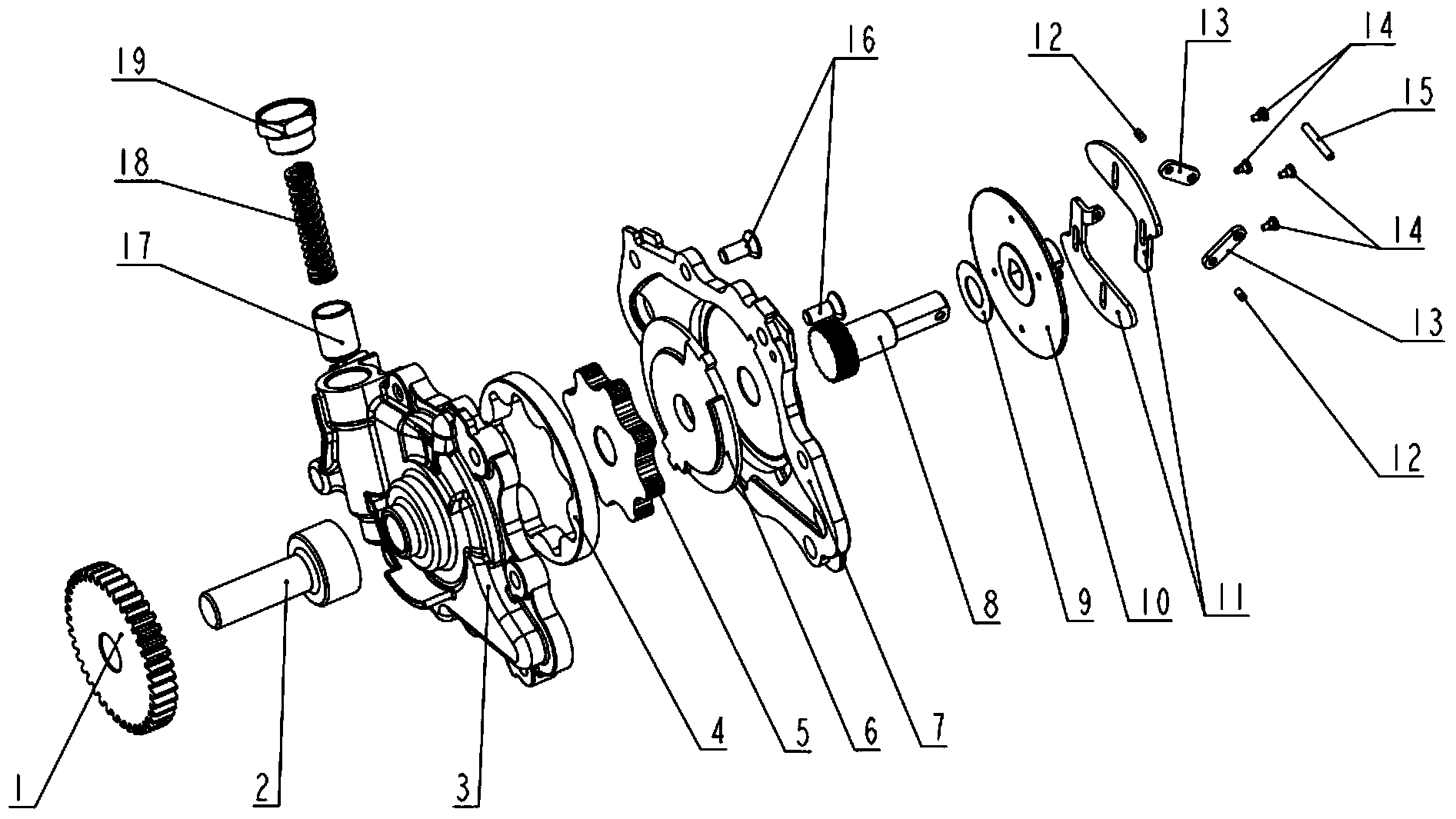
[0053] figure 1 It is an explosion diagram of a variable displacement rotor oil pump according to an embodiment of the present invention. Such as figure 1 As shown, the variable displacement rotor oil pump includes a pump casing 3 and a pump cover 7 facing the pump casing 3 , and bolts 16 are used to fixedly connect the pump casing 3 and the pump cover 7 . In an assembled state, the pump casing 3 and the pump cover 7 will define a receiving chamber between them for receiving the outer rotor 4 , the inner rotor 5 and the push plate 6 .

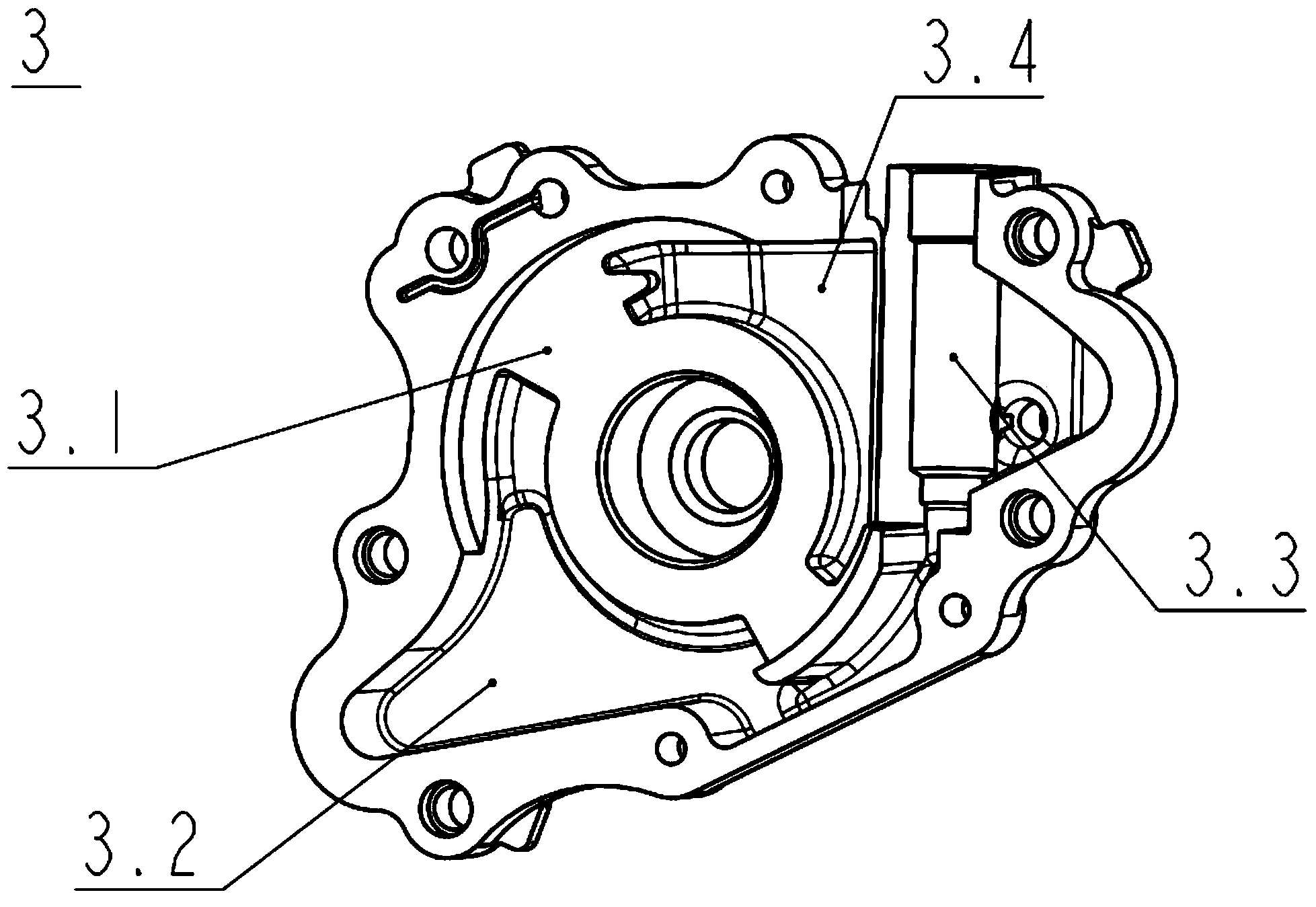
[0054] refer to image 3 , The pump casing 3 has a pump casing low-pressure oil zone 3.4 and a pump casing high-pressure oil zone 3.2 spaced apart. refer to Figure 5 , similarly, the pump cover 7 also has a pump cover low-pressure oil zone 7.1 and a pump cover high-pressure oil zone 7.5 spaced apart. In this way, when as Figure 12 and Figure 15 As shown, after the pump casing 3 and the pump cover 7 are assembled facing each other, in ...


PUM


Abstract

The invention relates to an oil pump, in particular to a variable displacement rotor oil pump. The rotor oil pump is provided with a rotating shaft penetrating through a pump shell and a pump cover; the rotating shaft is provided with a driving shaft and a following shaft which are connected mutually; the driving shaft is rotationally connected with the pump shell, and is driven by an external power source to rotate around an axis; the following shaft is fixedly connected with an internal rotor, and is connected with the driving shaft to ensure that the following shaft can synchronously rotate along with the driving shaft and is allowed to axially move along the axis relative to the driving shaft; an inertia actuating mechanism enables the internal rotor to move along the axis relative to an external rotor, so that the length of engagement of the internal rotor and the external rotor along the axis is changed. Because the following shaft can axially move along the axis relative to the driving shaft, the driving shaft can keep immobile basically along the axis direction. Therefore, an external power input gear and other external power sources are favorable for being stably jointed with a driving gear on the driving shaft.

Description

technical field [0001] The invention relates to an oil pump, in particular to a variable displacement rotor oil pump. Background technique [0002] The oil pump commonly used in automobile internal combustion engines is a fixed-displacement oil pump, and its oil flow is proportional to the engine speed. keep rising. Although the pressure relief valve will open after reaching a certain pressure to play a certain role in pressure regulation, the opening of the pressure relief valve is fixed and cannot be adjusted in real time, so the pressure in the oil passage will still be too high during high-speed operation. When the pressure is high, the high-pressure oil flows back, causing a certain power loss. But the lubrication of some parts in the engine does not need to increase the oil all the time as the engine speed increases. A fixed-displacement oil pump will increase the oil pressure in the engine oil passage, affect the lubrication effect, and lose the power of the engine...

Claims


Application Information

Patent Timeline
Patent Type & Authority Applications(China)
IPC IPC(8): F16N13/20
Inventor 白广松由毅沈源袁爽吴成明冯擎峰
Owner ZHEJIANG GEELY HLDG GRP CO LTD
Learn More