Liquid chlorine delivery system for producing chlorinated polyethylene

A chlorinated polyethylene and conveying system technology, applied in pipeline systems, gas/liquid distribution and storage, mechanical equipment, etc., can solve the problems of wasting manpower and material resources, affecting the chlorination reaction, affecting the continuous and stable output of liquid chlorine, etc. cost saving effect

Inactive Publication Date: 2014-05-07
山东泓利化学有限责任公司
View PDF6 Cites 6 Cited by
  • Summary
  • Abstract
  • Description
  • Claims
  • Application Information

AI Technical Summary

Problems solved by technology

Since chlorine is a very active element, it can react with most elements (or compounds). During the transportation of liquid chlorine, it will react with the substances in the pipeline or the pump body to produce impurities, which will cause blockage in the pump body, thus It affects the normal operation of the pump, affects the continuous and stable output of liquid chlorine, affects the chlorination reaction, and affects the product quality; and requires maintenance, cleaning and repair of the pump body, which

Method used


Image

  • Liquid chlorine delivery system for producing chlorinated polyethylene
  • Liquid chlorine delivery system for producing chlorinated polyethylene
  • Liquid chlorine delivery system for producing chlorinated polyethylene

Examples


Embodiment Construction

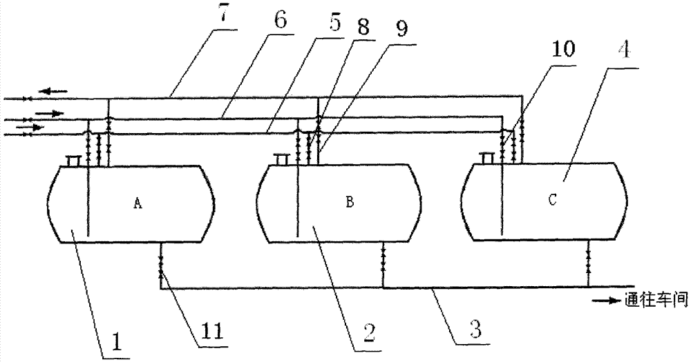
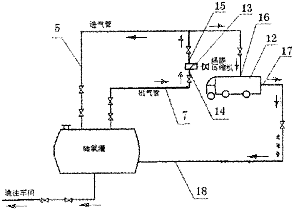
[0013] as attached figure 1 , 2 A liquid chlorine delivery system for the production of chlorinated polyethylene is shown, which includes three chlorine storage tanks A1, B2, and C4, a diaphragm air compressor 13, and the tops of the three chlorine storage tanks A1, B2, and C4. Air intake pipe 8, air outlet pipe 9, liquid chlorine inlet pipe 10 are respectively arranged on the surface, liquid chlorine outlet pipe 11 is respectively arranged on the bottom surface of each chlorine storage tank, and the air outlet pipe of each chlorine storage tank is connected on a total air outlet pipe 7, each The air inlet pipe is connected to a total air intake pipe 5, each liquid chlorine inlet pipe is connected to a total liquid chlorine inlet pipe 6, each liquid chlorine outlet pipe is connected to a total liquid chlorine outlet pipe 3, each tank Each pipe is provided with valve control; when producing chlorinated polyethylene, connect the total outlet pipe 7 with the air inlet 14 of the ...


PUM


Abstract

The invention discloses a liquid chlorine delivery system for producing chlorinated polyethylene. The liquid chlorine delivery system comprises a chlorine storage tank A, a chlorine storage tank B, a chlorine storage tank C and a membrane air compressor, and is characterized in that the top faces of the chlorine storage tank A, the chlorine storage tank B and the chlorine storage tank C are respectively provided with a gas inlet pipe, a gas outlet pipe and a liquid chlorine inlet pipe, the bottom faces of the chlorine storage tanks are respectively provided with a liquid chlorine outlet pipe, the gas outlet pipes of the chlorine storage tanks are connected to a total gas outlet pipe, the gas inlet pipes are connected to a total gas inlet pipe, the liquid chlorine inlet pipes are connected to a total liquid chlorine inlet pipe, the liquid chlorine outlet pipes are connected to a total liquid chlorine outlet pipe, and the pipes of each tank are provided with valves for control respectively. When the chlorinated polyethylene is produced, the total gas outlet pipe is connected with a gas inlet of the membrane air compressor, the total gas inlet pipe is connected with a gas outlet of the membrane air compressor, and the total liquid chlorine outlet pipe is connected with a workshop reaction kettle; when the liquid chlorine delivery system is used for liquid chlorine tank car unloading, the total gas outlet pipe is connected with the gas inlet of the membrane air compressor, the gas outlet of the membrane air compressor is connected with a compressed air opening of a tank car, and a liquid chlorine outlet of the tank car is connected with the liquid chlorine inlet pipes of the chlorine storage tanks.

Description

technical field [0001] The invention relates to a liquid chlorine delivery system for producing chlorinated polyethylene. Background technique [0002] Liquid chlorine is a yellow-green oily liquid that is poisonous. It is a low-pressure liquefied gas. In order to maintain the liquid state of liquid chlorine, the temperature of the chlorine storage tank must be controlled below 35°C. The periphery of the chlorine storage tank needs to be covered with insulation materials to prevent liquid chlorine Chlorine vaporizes into a gaseous form. Domestic production of chlorinated polyethylene mostly uses liquid chlorine. Some enterprises directly use small liquid chlorine cylinders, while enterprises with large liquid chlorine storage tanks use canned pumps or submerged pumps to transport liquid chlorine to the reactor. Since chlorine is a very active element, it can react with most elements (or compounds). During the transportation of liquid chlorine, it will react with the substa...

Claims


Application Information

Patent Timeline
IPC IPC(8): F17D1/02
Inventor 宗先双董丽娜
Owner 山东泓利化学有限责任公司
Why Eureka
Try Eureka