Measuring device and method for thrust loading of sliding thrust bearing, and application of measuring device and method

A thrust bearing and thrust load technology, which is used in measuring devices, force/torque/work measuring instruments, instruments, etc., can solve the problems of complex structure of hydraulic measuring system, modification of thrust bearing, and difficulty in realization, etc. Risk of safe operation, small structural changes, effect of unaffected lubricating properties

Active Publication Date: 2014-05-07
HUAZHONG UNIV OF SCI & TECH
View PDF9 Cites 10 Cited by
  • Summary
  • Abstract
  • Description
  • Claims
  • Application Information

AI Technical Summary

Problems solved by technology

The basic principle of this hydraulic thrust measurement scheme is very simple, but it is not easy to implement. On the one hand, an additional hydraulic system and oil leakage monitoring system need to be configured. On the other hand, the sealing of the piston is very critical, and the stroke of the piston must be controlled. Restricted to avoid excessive rigid body motion of the thrust ring during thrust changes
Generally speaking, the structure of the hydraulic measuring system is relatively complicated and the cost is high
US3828610 also discloses a hydraulic thrust measurement system, and its disadvantages also include the need to make major changes to the design of the thrust bearing structure

Method used


Image

  • Measuring device and method for thrust loading of sliding thrust bearing, and application of measuring device and method
  • Measuring device and method for thrust loading of sliding thrust bearing, and application of measuring device and method
  • Measuring device and method for thrust loading of sliding thrust bearing, and application of measuring device and method

Examples


Embodiment Construction

[0044] In order to make the object, technical solution and advantages of the present invention clearer, the present invention will be further described in detail below in conjunction with the accompanying drawings and embodiments. It should be understood that the specific embodiments described here are only used to explain the present invention, not to limit the present invention. In addition, the technical features involved in the various embodiments of the present invention described below can be combined with each other as long as they do not constitute a conflict with each other.

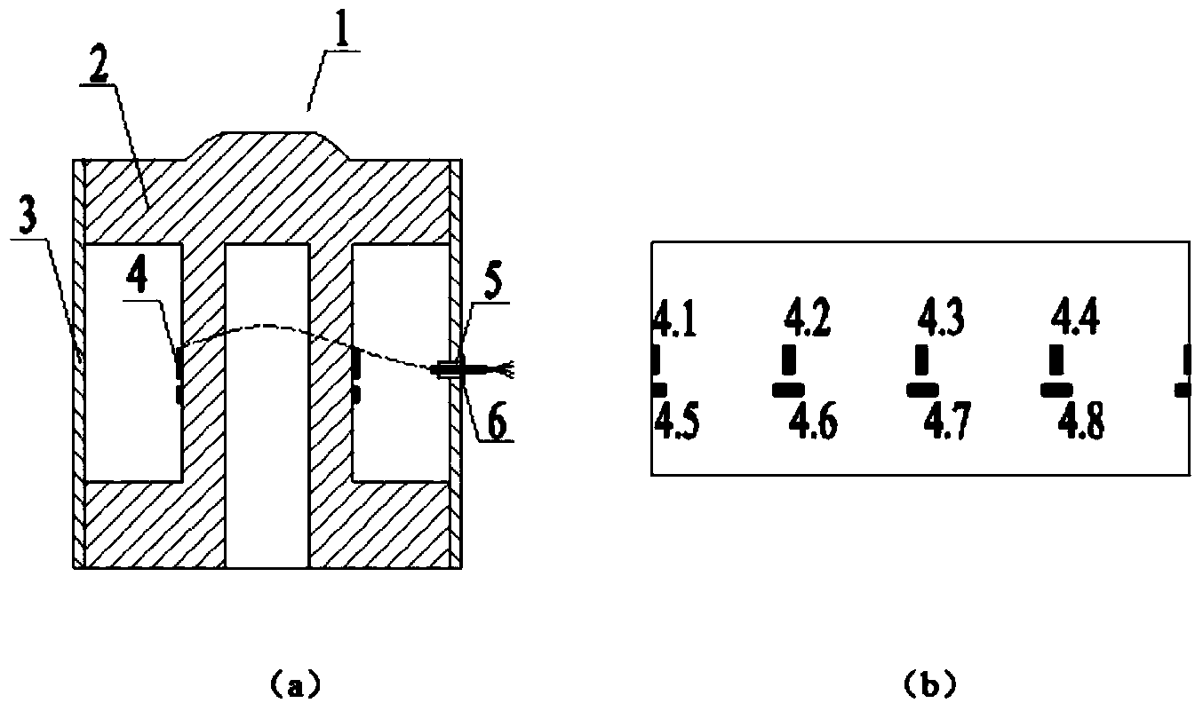
[0045] Such as figure 1 (a) is a schematic structural view of the resistance strain gauge of the embodiment of the present invention. The dynamometer 1 is composed of a steel cylinder 2 , a sealing structure 3 and a resistance strain gauge 4 . The upper part of the steel cylinder 2 is the bearing area, the middle part is the sticking area of ​​the resistance strain gauge 4, and the lower part ...


PUM


Abstract

The invention discloses a measuring device for thrust loading of a sliding thrust bearing. The measuring device comprises an annular base plate, wedge-shaped sliding blocks and resistance strain type force meters. The annular base plate is coaxially arranged between a thrust block holder and a thrust bearing shell in a sleeved mode. A plurality of radial holes are formed in the circumferential direction of the peripheral end face of the annular base plate. Through holes communicated with the radial holes are formed in the positions, corresponding to the radial holes, of the shell. The wedge-shaped sliding blocks are contained in the radial holes in the annular base plate through the through holes in the shell, and can be pulled out of the shell from the radial holes through the shell. The resistance strain type force meters are contained in the sliding blocks, and one end of each resistance strain type force meter abuts against and is connected with the thrust block holder. The invention further discloses a measuring device for the thrust loading of the sliding thrust bearing, and the application of the measuring device and method. According to the device and the method, the structure of the thrust bearing is slightly modified, and particularly the supporting structure of a thrust block is not changed; the lubrication performance of the thrust bearing is not affected, and the risks of safety running of the thrust bearing are not increased; meanwhile, the force meters can be easily overhauled and replaced under the condition that the shell of the thrust bearing is not disassembled.

Description

technical field [0001] The invention belongs to the field of monitoring the running state of a sliding thrust bearing, and in particular relates to a measuring device and method for thrust load of a sliding thrust bearing. Background technique [0002] Sliding thrust bearings (hereinafter referred to as thrust bearings) are used in rotating machinery such as ship propulsion systems, hydroelectric generator sets, thermal power generator sets, and water pump sets. Their basic function is to carry and transmit thrust loads. Thrust bearings are designed based on the theory of hydrodynamic lubrication, and are usually designed according to the full load condition and a certain bearing capacity reserve. However, theoretical design calculations are all done on the basis of certain assumptions, and it is impossible to include all possible factors that actually occur. Therefore, the measurement of the thrust load of the thrust bearing is very important. [0003] In the operating st...

Claims


Application Information

Patent Timeline
Patent Type & Authority Applications(China)
IPC IPC(8): G01L5/00
Inventor 赵耀张赣波储炜李天匀朱翔李良伟
Owner HUAZHONG UNIV OF SCI & TECH
Why Eureka
Try Eureka