Time correlation calculation diastimeter and measuring method

A time-correlation and rangefinder technology, applied in the field of distance measurement, can solve the problems of reduced distance measurement capability, unfavorable long-term debugging and use, and human eye hazards of high-power lasers.

Active Publication Date: 2015-11-25
BEIJING INST OF AEROSPACE CONTROL DEVICES
View PDF3 Cites 2 Cited by
  • Summary
  • Abstract
  • Description
  • Claims
  • Application Information

AI Technical Summary

Problems solved by technology

[0003] Although the current laser range finder can measure the distance at an ultra-long distance by virtue of the high penetrating power of the laser, it is difficult to fundamentally realize the long-distance ranging capability only by increasing the laser power and signal processing technology, and the high-power laser Use is extremely harmful to human eyes, which is not

Method used


Image

  • Time correlation calculation diastimeter and measuring method

Examples


Embodiment Construction

[0037] The specific implementation manner of a time-correlation calculation rangefinder of the present invention will be further described in detail below in conjunction with the accompanying drawings.

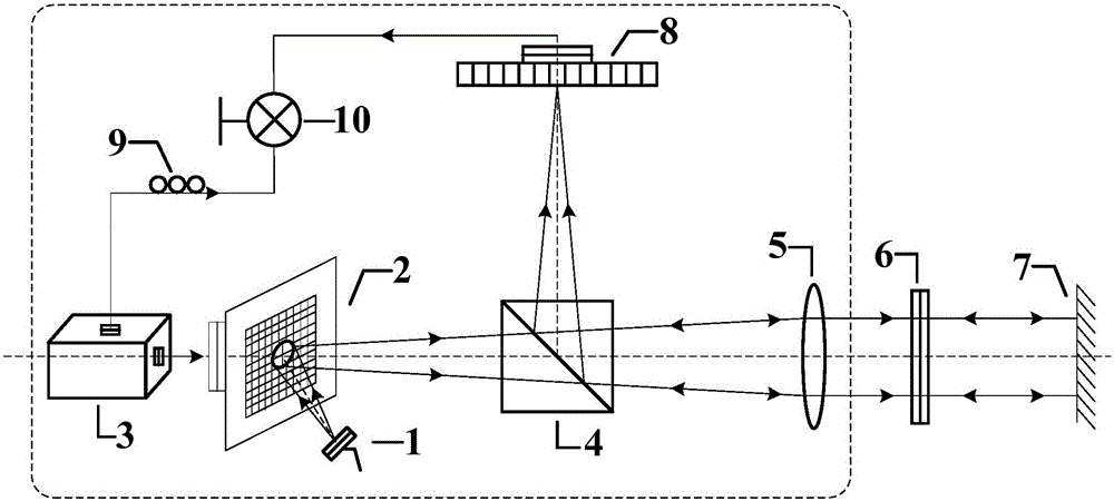
[0038] Such as figure 1 As shown in the figure: 1. Light source; 2. Digital micromirror array DMD; 3. Controller; 4. Beam splitter; 5. Lens; 6. Half mirror; . CCD (or point detector); 9. Delay device; 10. Coincidence measurement logic module; The coincidence measurement logic module includes a coincidence measurement logic unit and a calculation unit;

[0039] A time-correlated calculation rangefinder, comprising: a light source 1, a digital micromirror array DMD2, a controller 3, a beam splitter 4, a lens 5, a half-mirror 6, a reflective mirror 7 of a test piece, a CCD (or point Detector) 8, delayer 9, coincidence measurement logic module 10; Coincidence measurement logic module 10 comprises coincidence measurement logic unit and calculation unit;

[0040] The digital micro...


PUM


Abstract

A time correlation calculation diastimeter and a measuring method are provided. The time correlation calculation diastimeter includes a light source, a digital micromirror array DMD, a controller, a beam splitter, a lens, a semi-transmitting semi-reflecting mirror, a to-be-tested part reflective mirror, a CCD (or a point detector), a time delay unit, and a coincidence measurement logic module; the coincidence measurement logic module includes a coincidence measurement logic unit and a calculation unit. The coincidence measurement logic unit performs time coincidence measurement logic calculation on two channels of signals, and finally the distance between the to-be-tested part reflective mirror and the semi-transmitting semi-reflecting mirror is obtained. The diastimeter utilizes a time second-order correlation characteristic, can effectively reduce the distance measurement error caused by air disturbance factors, is simple in structural design and high in maneuverability, has key components all based on existing mature products, and has the characteristics of high technical maturity, relatively high realizability and the like.

Description

technical field [0001] The invention relates to a time-correlation calculation rangefinder and a measurement method, which belong to the field of distance measurement. Background technique [0002] The scale is the earliest tool used for distance measurement, but in long distances or complex environments, scale measurement becomes very difficult. During World War II, Britain first developed the ranging radar, which realized the rapid measurement of the instantaneous distance of various targets at different azimuth angles at a fixed point, and achieved a historic breakthrough in ranging technology. Later, with the development of electromagnetic and laser technology, lasers were gradually used in the field of distance measurement, and in 1961, the Hughes Aircraft Company of the United States developed the first laser rangefinder. The advantages of high resolution and strong anti-interference have been developed rapidly over a long period of time, and various forms of ranging ...

Claims


Application Information

Patent Timeline
IPC IPC(8): G01C3/00G01C3/02
CPCG01C3/00G01C3/02
Inventor 赵连洁杨然李明飞霍娟张安宁莫小范刘院省
Owner BEIJING INST OF AEROSPACE CONTROL DEVICES
Why Eureka
Try Eureka