Three-dimensional picture display device

A technology for display devices and stereoscopic images, which is applied to identify the directions of devices, instruments, optics, etc., and can solve problems such as the influence of display effects and different directions

Active Publication Date: 2014-05-07
SHANGHAI TIANMA MICRO ELECTRONICS CO LTD
View PDF5 Cites 16 Cited by
  • Summary
  • Abstract
  • Description
  • Claims
  • Application Information

AI Technical Summary

Problems solved by technology

[0011] A plurality of BM stripes B, the direction of the plurality of BM stripes can be more than two different directions, the BM stripes in each direction interact with the grating A to generate moiré fringes, and the moiré fringes different directions, different moiré fringes on the entire stereoscopic image display device will be superimposed and affect the display effect

Method used


Image

  • Three-dimensional picture display device
  • Three-dimensional picture display device
  • Three-dimensional picture display device

Examples


Embodiment 1

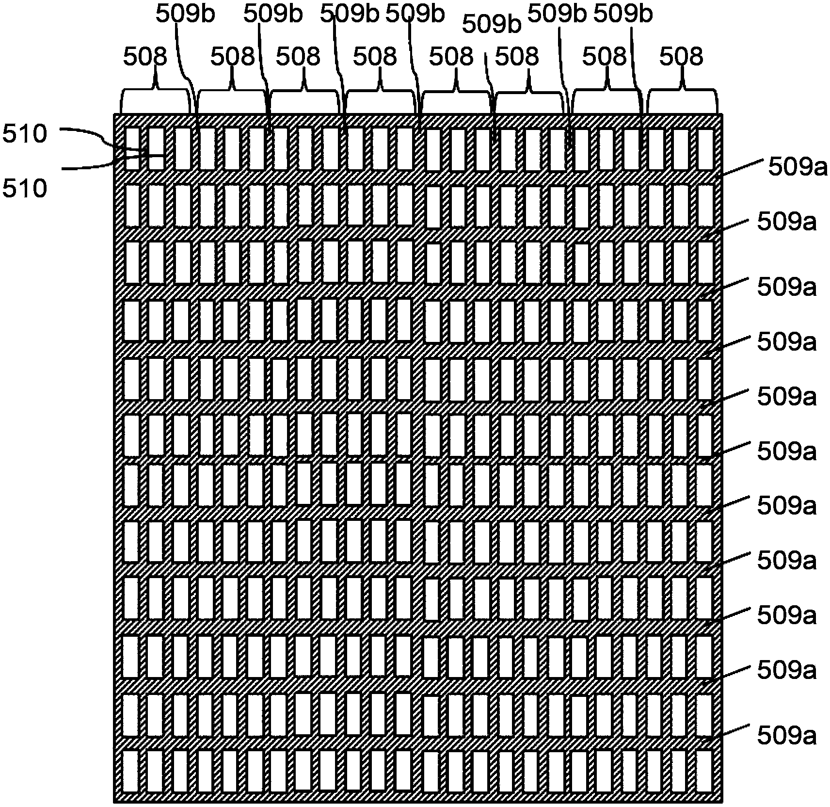
[0056] Such as Figure 5 As shown, it is a schematic diagram of pixel design of a stereoscopic display device according to an embodiment of the present invention.

[0057] The stereoscopic display device includes a flat-panel display device, and the flat-panel display device includes a TFT (Thin Film Transistor) substrate 501 and a CF (Color Filter) substrate 502 disposed opposite to each other, and a substrate disposed on the TFT substrate 501 and the CF substrate 502 between the liquid crystal (not shown).

[0058] As far as the TFT substrate is concerned, a plurality of scanning lines 503 and a plurality of data lines 504 are arranged on the TFT substrate 501, and the plurality of scanning lines 503 and the plurality of data lines 504 are intersected to define a plurality of sub-pixels 505 , in this embodiment for illustration, only six sub-pixels 505 arranged in three rows and two columns are shown. Each sub-pixel 505 is controlled by a TFT switch element 506, and each T...

Embodiment 2

[0082] The difference between the second embodiment and the first embodiment is that the angle between the first part of the first light shielding part of each sub-pixel and the second part of the first light shielding part is greater than 0 degrees and less than 90 degrees.

[0083] Figure 9 is a top view of a sub-pixel, such as Figure 9 As shown, the first part 801a of the first light-shielding part is in the same direction as the sub-pixel row, and the second light-shielding part 802 is arranged on the sub-pixel, and the second light-shielding part 802 divides each of the sub-pixels into three two parts 803a, 803b, 803c with the same shape and size, the second part 801b of the first light-shielding part is located between each sub-pixel of each row of sub-pixels and parallel to the second light-shielding part 802, the first light-shielding part The angle between the second part 801b of the first light shielding part 801a and the first part 801a of the first light shieldi...

Embodiment 3

[0088] In this embodiment, the flat panel display device in the stereoscopic display device is an embodiment of an FFS (Fringe Field Switching, fringe field switching) type liquid crystal display device or an IPS (In Panel Switching, in-plane field switching) type liquid crystal display device. The FFS type liquid crystal display device or the IPS type liquid crystal display device, its display principle is that the pixel electrode and the common electrode driving the liquid crystal are located on the same substrate, generally a TFT substrate, and the liquid crystal display devices of the two modes are relatively The traditional TN (Twisted Nematic, twisted nematic) has a wider display viewing angle, but the liquid crystal molecules in the middle area between the adjacent pixel electrodes and the common electrode do not have a clear deflection direction and produce domain lines. From a visual point of view, there will be bars or seams with uneven colors in this area, which also...


PUM


Abstract

The invention provides a three-dimensional display device which comprises a panel display device. The panel display device comprises a plurality of lines of sub pixels and first shading portions arranged between the sub pixels. Colors of the color sub pixels on each line are identical, each sub pixel is controlled by a TFT, and each sub pixel is divided into m portions by second shading portions, wherein m is larger than 1 and is an integer. The sub pixels are divided into multiple portions through the shading portions, so that the separation distance of moire fringes is effectively reduced, and therefore the problem of moire fringe interference is solved.

Description

technical field [0001] The invention relates to the field of stereoscopic display, in particular to a stereoscopic image display device capable of effectively reducing moire fringes. Background technique [0002] The basic principle of stereoscopic display technology is to use the parallax of the left and right eyes of people to provide the display images to the left and right images of the left and right eyes respectively, and then mix them into a stereoscopic image by the observer's brain. [0003] Stereoscopic image display devices can be divided into glasses-wearing type and naked-eye type, and the naked-eye type can be further divided into parallax barrier, lenticular lens, directional backlight, and multiple screens. The principles of the stereoscopic display device of the parallax barrier and the lenticular lens technology are respectively introduced below. [0004] Parallax Barrier Technology [0005] The parallax barrier technology is to add a liqui...

Claims


Application Information

Patent Timeline
Patent Type & Authority Applications(China)
IPC IPC(8): G02F1/1335G02B27/22G02B27/60G09F9/33G02B30/27
CPCG02F1/1335G02B27/2214G09F9/33G02F1/133512G02B30/27
Inventor 牛磊吴章奔汪星辰马骏
Owner SHANGHAI TIANMA MICRO ELECTRONICS CO LTD
Why Eureka
Try Eureka