
A wave soldering system and control method for led plug-in light board

A wave soldering, LED lamp technology, applied in program control, computer control, general control system, etc., can solve the problems of increased pump loss, waste of solder, etc., to reduce waste, reduce wave peaks, and avoid excessive generation of tin dross Effect

Inactive Publication Date: 2016-11-23
NANTONG SUHE LAMP PARTS
View PDF5 Cites 0 Cited by
  • Summary
  • Abstract
  • Description
  • Claims
  • Application Information

AI Technical Summary

Problems solved by technology

[0007] The technical problem to be solved by the present invention is to provide a wave soldering system and its welding method for LED plug-in light boards. By adding a tin slag removal device and an anti-oxidation device, the tin slag can be removed in time when there is too much tin slag, and the oxidation can be reduced as much as possible. Reduce the generation of scum, effectively solve the problems of solder waste and pump loss increase caused by excessive scum in the wave soldering process in the prior art

Method used


Image

  • A wave soldering system and control method for led plug-in light board

Examples


Embodiment Construction

[0022] Below in conjunction with accompanying drawing, structure and working process of the present invention will be further described.

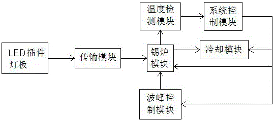
[0023] Such as figure 1 As shown, a wave soldering system for LED plug-in light boards includes a transmission module, a temperature detection module, a tin furnace module, a cooling module, a wave control module, and a system control module. The board is transferred to the tin furnace module. The tin furnace module includes a furnace and a tin furnace nozzle. The bottom of the furnace is provided with a heater, the top is provided with a tin furnace nozzle, and the inside of the furnace is provided with solder. The cooling module is used for cooling welding After the LED plug-in light board, the temperature detection module detects the temperature of the solder in the furnace and the cooling temperature of the cooling module, and the system control module heats the solder in the furnace to a preset temperature according to the data of the ...


PUM


Abstract

The invention discloses a wave soldering system for an LED plug-in lamp panel. The wave soldering system comprises a transmission module, a temperature detecting module, a solder machine module, a cooling module, a wave control module and a system control module. The solder machine module further comprises a solder splash removing device, an anti-oxidation device and an LED plug-in lamp panel detecting device. The solder splash can be automatically filtered through the system, the anti-oxidation device can effectively isolate contact between soldering tin and the atmosphere, and the solder splash is prevented from being produced. The invention further discloses a control method of the wave soldering system for the LED plug-in lamp panel, the depth of the LED plug-in lamp panel dipped into a wave crest is adjusted, time of a plug-in lamp base on the LED plug-in lamp panel passing by the wave crest is controlled, soldering efficiency and quality are effectively improved, and cost is saved.

Description

technical field [0001] The invention belongs to the technical field of LED applications, and in particular relates to a wave soldering system for an LED plug-in lamp board and a control method thereof. Background technique [0002] Wave soldering refers to spraying molten solder (lead-tin alloy) into the solder wave peak required by the design through an electric pump or electromagnetic pump. It can also be formed by injecting nitrogen into the solder pool, so that the pre-installed components The printed board realizes the soldering of the mechanical and electrical connection between the solder end of the component or the pin and the pad of the printed board through the solder wave. [0003] Wave soldering process: Insert the component into the corresponding component hole → pre-coat flux → preheat → wave soldering → cool down → cut off excess plug-in feet → check. [0004] Peak soldering has a new welding process with the enhancement of people's awareness of environmental...

Claims


Application Information

Patent Timeline
Patent Type & Authority Patents(China)
IPC IPC(8): H05K3/34G05B19/042
Inventor 孟玉喜陈晓军邹栋林
Owner NANTONG SUHE LAMP PARTS
Learn More