Mounting structure of fan and heat radiating device

A technology of installation structure and fan position, which is applied to components of pumping devices for elastic fluids, cooling/ventilation/heating transformation, electrical equipment construction parts, etc. Bad and other issues

Inactive Publication Date: 2014-05-07
DELTA ELECTRONICS POWER (DONGGUAN) CO LTD
View PDF8 Cites 2 Cited by
  • Summary
  • Abstract
  • Description
  • Claims
  • Application Information

AI Technical Summary

Problems solved by technology

[0004] The purpose of the present invention is to provide a fan installation structure to solve the technical problems in the prior art that it takes a lot of time to install the fan and it is easy to cause poor installation or even make the fan scrapped

Method used


Image

  • Mounting structure of fan and heat radiating device
  • Mounting structure of fan and heat radiating device
  • Mounting structure of fan and heat radiating device

Examples


Embodiment Construction

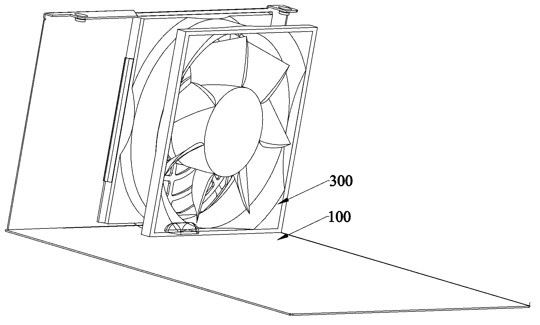
[0036] In the following embodiments described with reference to the accompanying drawings, the fan 300 is installed between the first mounting plate 100 taking the lower cover of the casing as an example and the second mounting plate 200 taking the upper cover of the casing as an example, but the present invention does not Not limited to this.

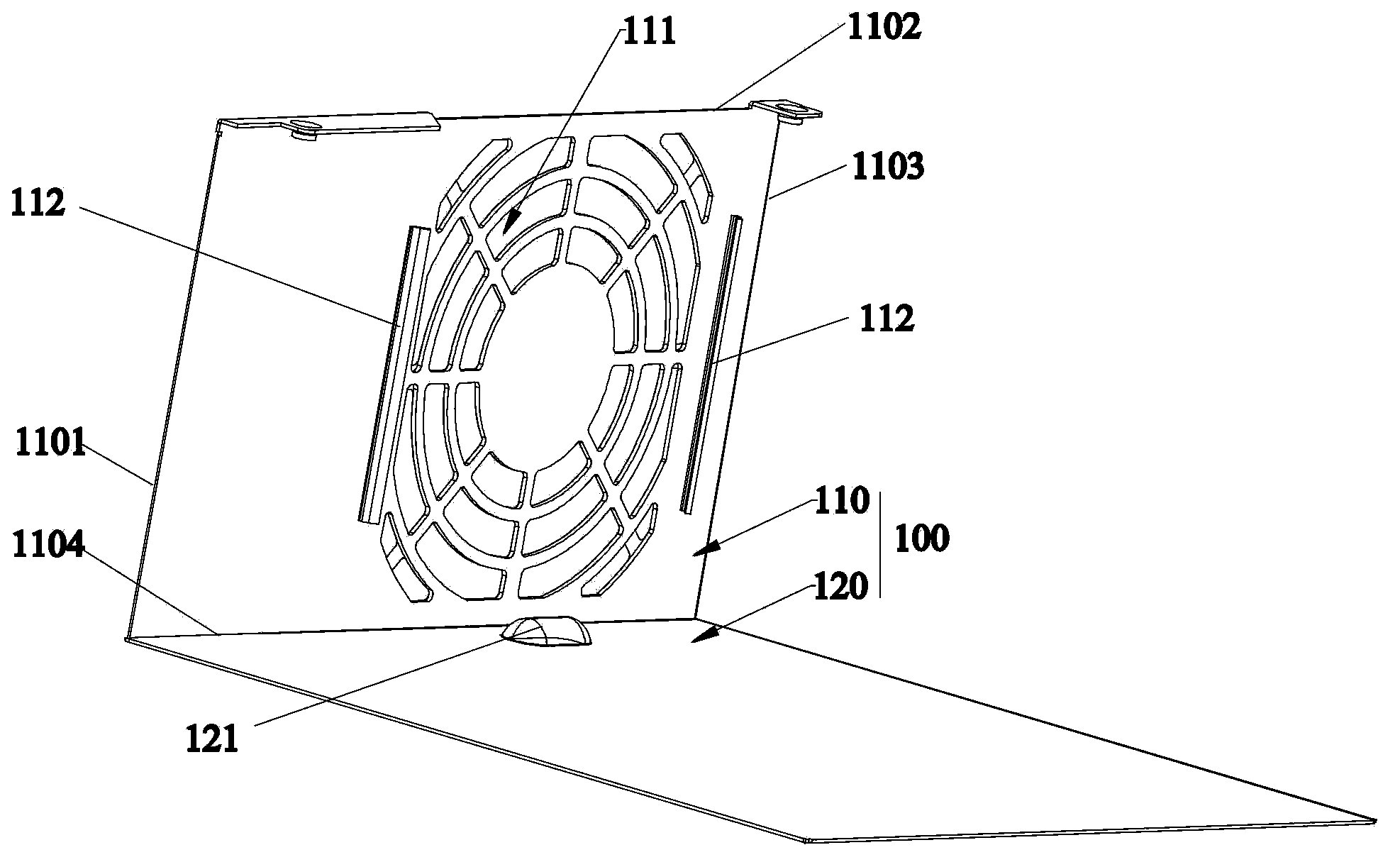
[0037] Such as Figure 1~Figure 4 As shown, the present invention provides a fan installation structure, which includes a first mounting plate (such as a lower case cover) 100, a second mounting plate 200 (such as a case upper cover) connected to the first mounting plate 100, mounted on the second A fan 300 mounted on the board 100 .

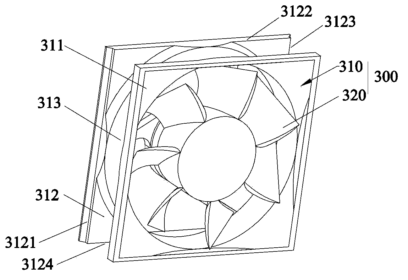
[0038] The fan 300 includes a fan frame 310 and fan blades 320 arranged in the fan frame 310. The fan frame 310 has an upper plate 311 and a lower plate 312 spaced apart from each other, and an annular connection between the upper plate 311 and the lower plate 312. Item 313. The lower plate 312 includ...


PUM


Abstract

The invention provides a mounting structure of a fan. The fan comprises a fan frame and fan blades arranged in the fan frame. The fan frame is provided with an upper plate, a lower plate and an annular connecting piece which is connected between the upper plate and the lower plate. The lower plate comprises a first side, a second side, a third side and a fourth side which are sequentially connected. The mounting structure comprises a first mounting plate and a second mounting plate. The fan is installed on the first mounting plate which comprises a bottom plate and a side plate which is perpendicular to the bottom plate. The bottom plate comprises a first side, a second side, a third side and a fourth side which are sequentially connected. The side plate is connected to the fourth side of the bottom plate which is provided with a ventilation area corresponding to the fan position. Two folded sides which extend to the ventilation area are arranged around the ventilation area, and thus sliding grooves are formed between the two folded sides and the bottom plate such that the fan slides to a position to be fixed from the second side of the bottom plate on the first mounting plate. The invention also provides a heat radiating device with the above fan mounting structure.

Description

technical field [0001] The invention relates to a mounting structure, in particular to a fan mounting structure and a cooling device. Background technique [0002] At present, as the operating frequency of various electronic components continues to increase, more and more heat is generated during operation, so it is particularly important to ventilate and dissipate heat for various electronic devices. [0003] The existing fans are generally provided with fixing holes at the four corners of the fan frame, and then four locking screws are inserted to fix the fan. However, this fixing method requires tools such as a screwdriver, and requires four repetitive operations, which will result in higher man-hours. And when using screws to lock the fan, if the torque of the screwdriver is improper, the fixing hole will be damaged and the installation will be bad. The locking screw with self-tapping teeth will engage the plastic fan frame, and the whole fan will be scrapped due to rei...

Claims


Application Information

Patent Timeline
Patent Type & Authority Applications(China)
IPC IPC(8): H05K7/20
CPCF04D29/646H05K7/20172
Inventor 李卫国巴志超
Owner DELTA ELECTRONICS POWER (DONGGUAN) CO LTD
Why Eureka
Try Eureka