Structure of pressure-resistant oil tank and manufacturing method thereof

A manufacturing method and technology for fuel tanks, which are applied in the field of fuel tanks, can solve the problems of poor tensile force, quality, and scrapping of fuel tanks, and achieve the effects of improving connection tightness, high structural quality, and low scrapping risk.

Active Publication Date: 2019-12-10
德安福(天津)汽车技术有限公司
View PDF9 Cites 2 Cited by
  • Summary
  • Abstract
  • Description
  • Claims
  • Application Information

AI Technical Summary

Problems solved by technology

[0006] The above-mentioned fuel tank requires strict coupling between the various parts during the molding process, and the coupling method is also a direct insertion type. This coupling method is easy to squeeze, thin or even break the molten material strip, which brings the risk of quality or scrap , the fuel tank has poor tensile strength

Method used


Image

  • Structure of pressure-resistant oil tank and manufacturing method thereof
  • Structure of pressure-resistant oil tank and manufacturing method thereof
  • Structure of pressure-resistant oil tank and manufacturing method thereof

Examples


Embodiment 1

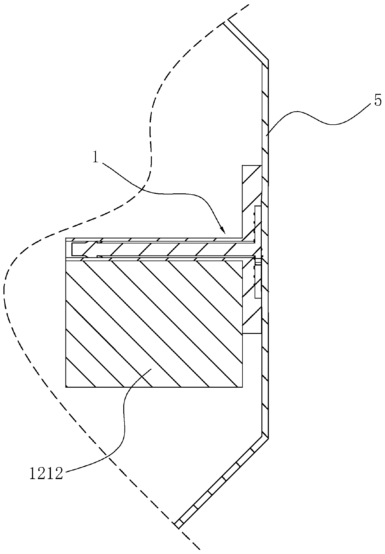
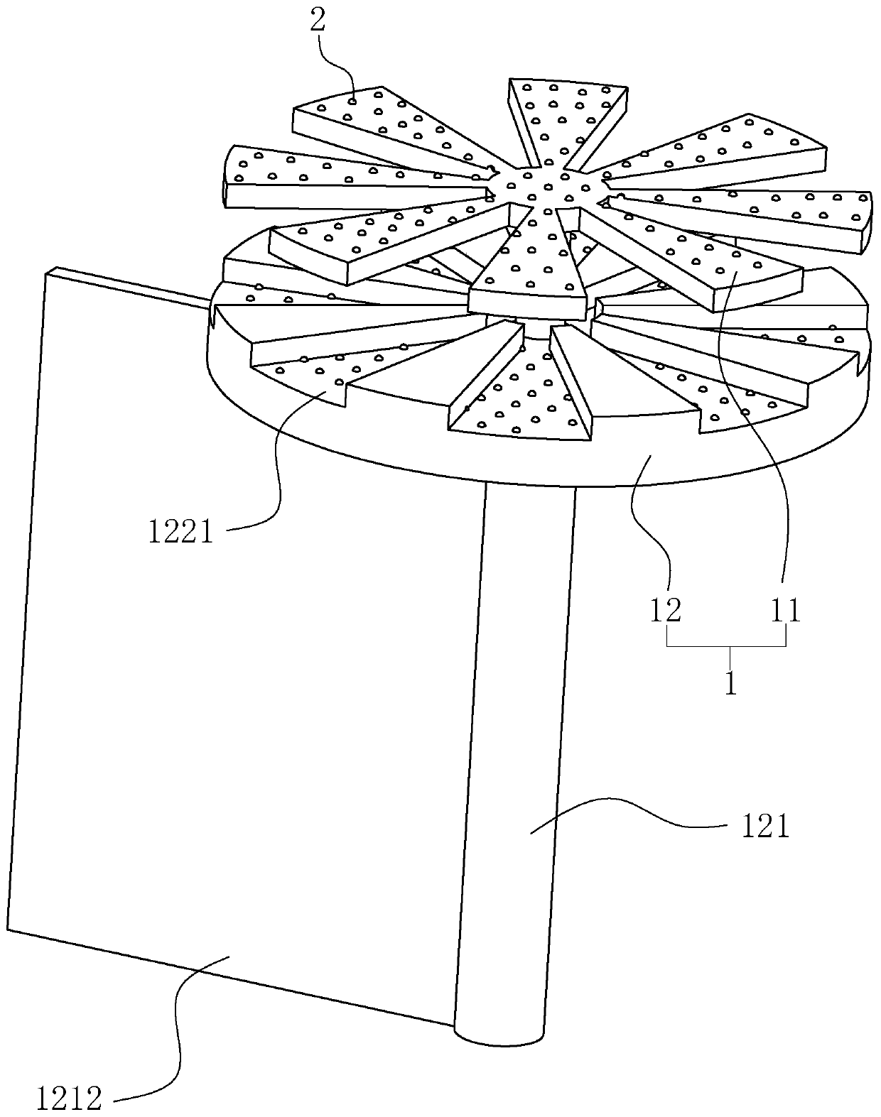
[0051] A structure of a pressure-resistant oil tank, such as figure 1 As shown, including the fuel tank body 5, the inner wall of the fuel tank body 5 is fixedly provided with at least one connecting piece 1, and the connecting piece 1 is scalded and fixed when the fuel tank body 5 is still in the state of the molten parison, so that the connecting piece 1 and the fuel tank body 5 can be integrally fixed, and the connecting piece 1 can withstand high tensile force, so that when the fuel tank body is used in a PHEV vehicle, it can be applied to a larger negative pressure to positive pressure range, thereby improving the strength and quality of the fuel tank body 1 , the anti-wave plate 1212 can also be fixedly connected on the connecting piece 1 to play the role of anti-wave, or other components can be fixed on the connecting piece 1 as required. Compared with the prior art, the connection method between the connector 1 and the fuel tank body 5 does not require a welding proces...

Embodiment 2

[0059] A method for manufacturing a pressure-resistant oil tank, comprising the following steps:

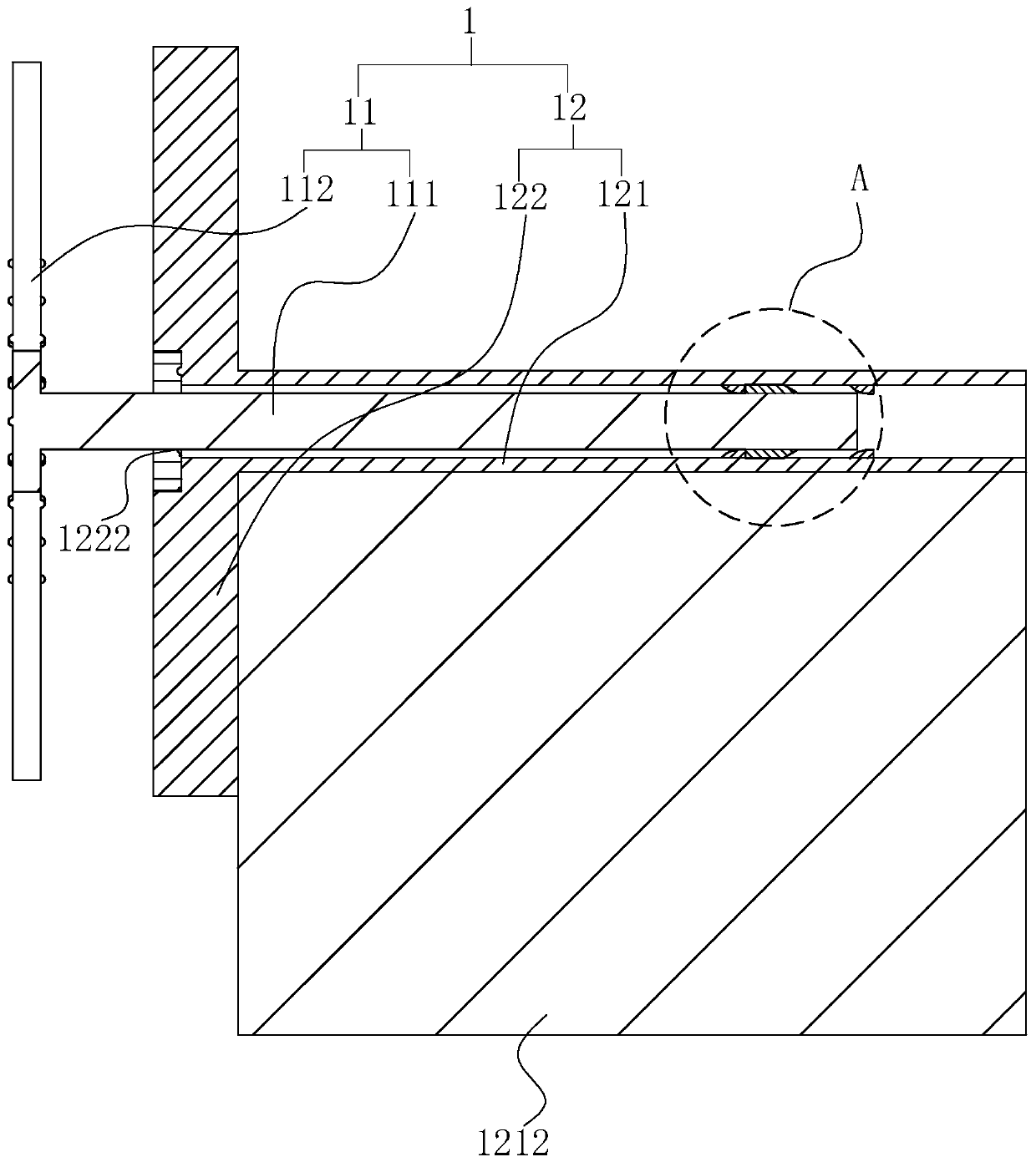
[0060] S1. Install the connector 1. When installing, install the installation rod 111 through the socket 1222 and insert it into the sleeve 121 until the snap ring 1111 passes over the shoulder 1211 once. At this time, the gap between the installation disk 112 and the mating disk 122 is the installation disk. Radius distance of 112;

[0061] S2. Send the connector 1 into the blow mold 3. The blow molding machine is equipped with a feeder 4 for sending the connector 1 into the blow mold 3. The feeder 4 is fixed with a temporary connector 1 and drives the connection. Part 1 translational feeding drive 41, the feeding drive 41 is preferably a cylinder; as Figure 7 shown;

[0062] S3, the extruder extrudes the molten parison, and then the parison is put into the blow mold 3, and the blow mold 3 starts the mold closing process; the blow mold 3 is provided with a shaft hole 31 commu...


PUM


Abstract

The invention relates to a structure of a pressure-resistant oil tank and a manufacturing method thereof. According to the main points of the technical scheme, the manufacturing method of the pressure-resistant oil tank comprises the following steps that S1, a connection part is installed, an installation rod is inserted into a sleeve from one end of a matching disc during installation, and a gapis reserved between an installation disc and the matching disc; S2, the connection part is fed into a blow molding mold through a feed part, a blow molding machine blows out a molten parison, the parison is put into the mold, and the blow molding mold is closed; S3, the installation disc makes contact with the parison and presses the parison into a shaft hole, a pressing driving part pushes a shaft sleeve to move along the shaft hole and rotates at the same time, and the shaft sleeve pushes the installation disc to abut against the matching disc; and S4, the blow molding mold is opened, the feed part is taken out from the blow molding mold, then the blow molding mold is closed again, the mold is opened again after the parison is cooled, and the effect that connection strength and stabilitybetween an anti-wave plate and the inner wall of the pressure-resistant oil tank are improved is achieved.

Description

technical field [0001] The invention relates to the technical field of fuel tanks, in particular to a structure of a pressure-resistant fuel tank and a manufacturing method thereof. Background technique [0002] With the severe environmental protection situation, the voice of gradually reducing the emissions of fuel vehicles or even stopping the production of fuel vehicles is increasing. At present, pure electric vehicles have the problems of short battery life and high maintenance costs in the later period. There are still many technical problems that have not been overcome for hydrogen energy vehicles. Therefore, PHEV models, as a transitional model, are increasingly valued by various OEMs. [0003] For the fuel tank system of general fuel vehicles, since the internal combustion engine is always in the running state during operation, the oil pump keeps the pressure of the fuel tank at 4-10KPa all the time, but for PHEV vehicles, the vehicle may be driven by electricity for...

Claims


Application Information

Patent Timeline
Patent Type & Authority Applications(China)
IPC IPC(8): B29C49/20
CPCB29C49/20
Inventor 石志刚邢天龙赵淳张红明
Owner 德安福(天津)汽车技术有限公司
Why Eureka
Try Eureka