Improved braking for rail vehicles

A technology for rail vehicles and rails, applied in the field of control devices for braking equipment

Active Publication Date: 2016-05-18
KNORR BREMSE SYST FUR SCHIENENFAHRZEUGE GMBH
View PDF5 Cites 0 Cited by
  • Summary
  • Abstract
  • Description
  • Claims
  • Application Information

AI Technical Summary

Problems solved by technology

However, this contact has only a limited ability to withstand braking forces

Method used


Image

  • Improved braking for rail vehicles
  • Improved braking for rail vehicles

Examples


Embodiment Construction

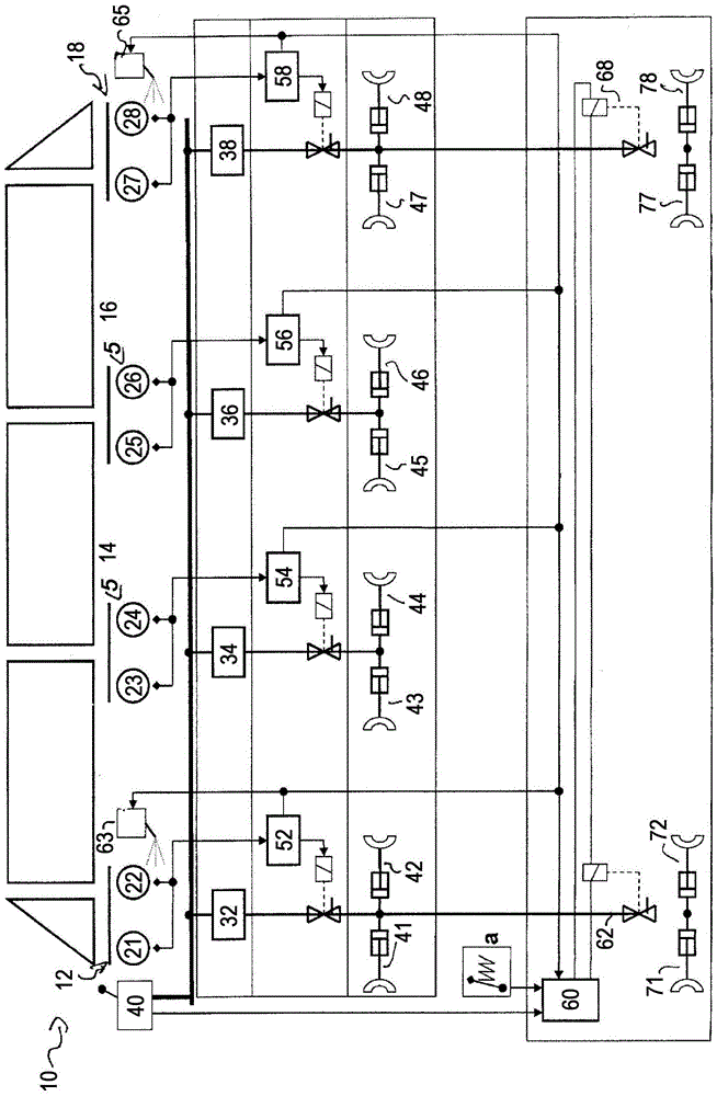
[0019] figure 1 The rail vehicle 10 is schematically shown. The rail vehicle 10 has a plurality of carriages, and these carriages include a first bogie 12, a second bogie 14, a third bogie 16 and a fourth bogie 18. Axles 21 and 22 are arranged on the first bogie 12. Axles 23, 24 are arranged on the second bogie 14, while axles 25, 26 are arranged on the bogie 16 and axles 27, 28 are arranged on the bogie 18. The pressure-acting brake devices are respectively assigned to the axles of the bogie, and the brake pressure is provided to the brake devices through a common control valve. Therefore the first control valve 32 is assigned to the first bogie 12, the second control valve 34 is assigned to the second bogie 14, the third control valve 36 is assigned to the third bogie 16 and the fourth control valve 38 is assigned to the fourth steering frame. The control valves 32, 34, 36, 38 are connected to the main pressure line, which supplies control pressure to the control valves 32...


PUM


Abstract

The invention relates to a control device (60) for a braking system of a rail vehicle (10), wherein the braking system has at least one first braking device (41-48) and at least one second braking device ( 41-48; 71, 72, 77, 78), these braking devices can be manipulated with steering force during braking. The first braking device (41-48) and the second braking device (41-48; 71, 72, 77, 78) are adhesion-dependent braking devices. The control device (60) is able to generate and / or receive a lack of adhesion signal, which indicates insufficient adhesion of the first and / or second braking device (41-48), and is further designed to, when braking The first and / or the second braking device (41-48; 71, 72, 77, 78) is actuated with an increased actuation force during maneuvering when there is a lack of adhesion signal. Furthermore, the invention relates to a braking system for a rail vehicle having such a control device, a corresponding rail vehicle and a method for controlling a braking system of a rail vehicle by means of a control device.

Description

Technical field [0001] The invention relates to a control device for a brake device of a rail vehicle, the brake device having at least one first brake device and at least one second brake device, and to a brake device for a rail vehicle , A rail vehicle and a method for controlling a brake device of a rail vehicle. Background technique [0002] Different types of brakes are used to brake rail vehicles. As the service brake, known brakes that depend on adhesion are generally used. This adhesion-dependent brake transmits braking force through the contact between the wheels and the track. However, this contact has only a limited ability to withstand braking force. This ability to withstand braking force via wheel-track contact is determined by the adhesion between the wheel and the track, and this adhesion can be parameterized by the adhesion coefficient. If the steering force used to brake the wheel exceeds the braking force that can be transmitted by the adhesion force, the w...

Claims


Application Information

Patent Timeline
Patent Type & Authority Patents(China)
IPC IPC(8): B60T8/17B60T13/74B61H7/06
CPCB60T8/1705B61H7/06B60T13/748B60T13/665B60T17/228B61H13/00
Inventor 赖因霍尔德·迈尔托马斯·拉泽尔马克-奥利弗·赫尔登约尔格-约翰内斯·瓦赫
Owner KNORR BREMSE SYST FUR SCHIENENFAHRZEUGE GMBH
Why Eureka
Try Eureka