Hydraulic vehicle braking system with anti-locking arrangement

A hydraulic braking and anti-lock braking technology, applied in the direction of brakes, brake components, brake types, etc., can solve problems such as excessive tire wear, front wheel being locked, brake slipping, etc.

Inactive Publication Date: 2003-02-26
ROBERT BOSCH GMBH
View PDF4 Cites 0 Cited by
  • Summary
  • Abstract
  • Description
  • Claims
  • Application Information

AI Technical Summary

Problems solved by technology

The disadvantage of this type of braking system in anti-lock operation is that the braking pressure of the rear wheel brakes cannot be higher than that of the front wheel brakes
If we want the brake pressure of the rear brakes to be higher than the reliable brake pressure of the front brakes, the front wheels must be overbraked for a short period of time, which may cause brake slippage, loss of control and excessive tire wear
The reason why it is desirable to make the braking pressure of the rear wheel brakes higher than the braking pressure of the front wheel brakes is that when the accelerator pedal is released, the engine driving the front wheels of the car will brake the front wheels. On snow and slippery ice, this can quickly lead to the danger of the front wheel being locked
In addition, another reason why it is desirable to make the braking pressure of the rear wheel brakes higher than that of the front wheel brakes is that when the vehicle decelerates on a road with poor adhesion, the deceleration effect of the rear wheels may be greater than that on a road with strong adhesion.

Method used


Image

  • Hydraulic vehicle braking system with anti-locking arrangement
  • Hydraulic vehicle braking system with anti-locking arrangement
  • Hydraulic vehicle braking system with anti-locking arrangement

Examples


Embodiment Construction

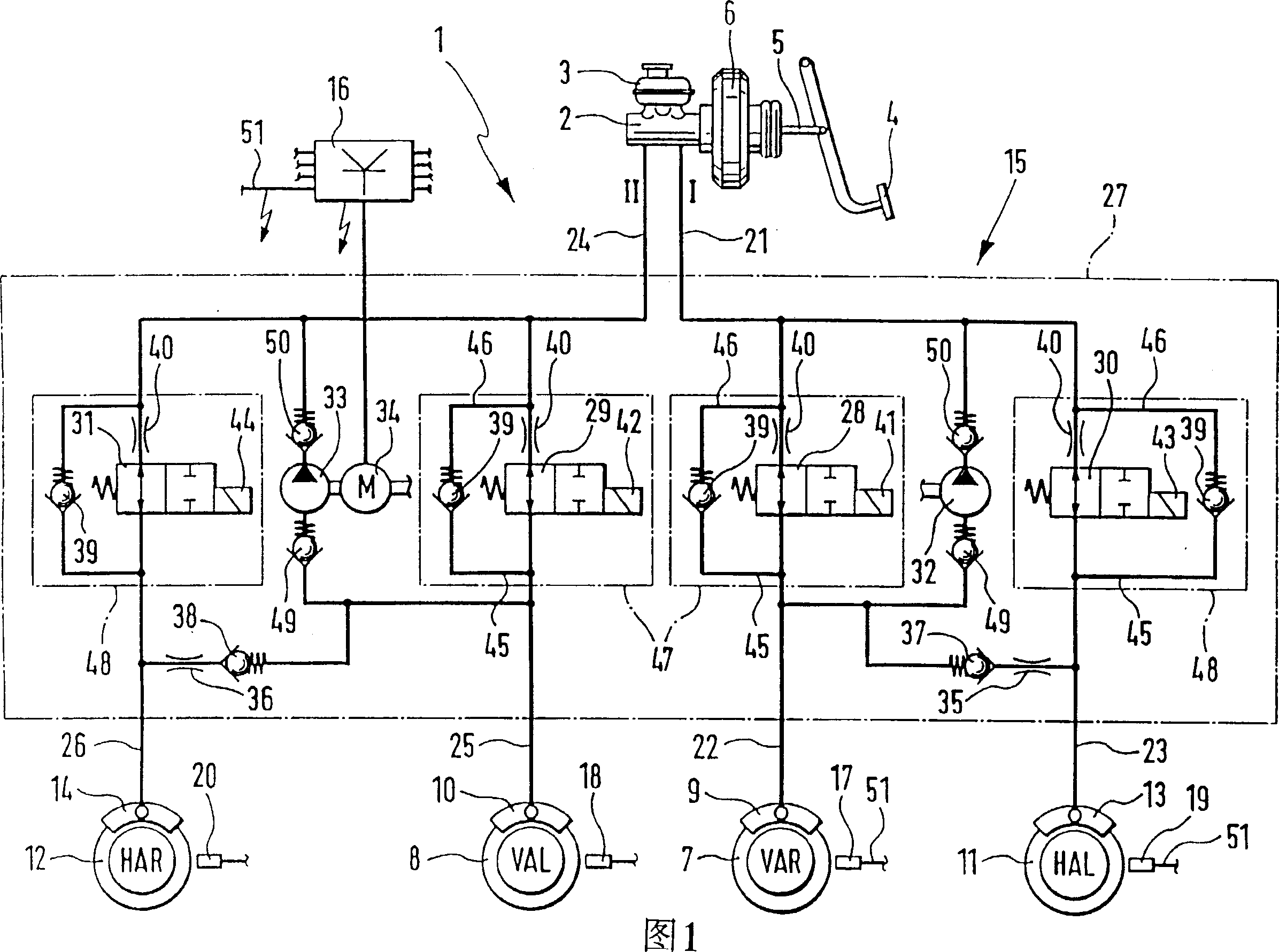
[0027] The automobile hydraulic braking system in Fig. 1 has a dual-circuit master brake cylinder 2 comprising a reserve oil tank 3, a brake pedal 4, a pedal lever 5, a brake force booster 6, two brake circuits I and II, Two front wheel brakes 7 and 8 with wheel brake cylinders 9 and 10, two rear wheel brakes 11 and 12 with wheel brake cylinders 13 and 14, an antilock device 15 and associated antilock brake Controller 16 of device 15 and wheel rotation sensors 17 , 18 , 19 and 20 .

[0028] Brake circuit 1 comprises a main brake circuit 21 that is sent from the main brake cylinder 2 and leads to the anti-lock brake device 15 and two wheels that are sent from the anti-lock brake device 15 and passed to the wheel brake cylinders 9 and 13. Moving circuits 22 and 23. Brake circuit II likewise includes a main brake circuit 24 and two wheel brake circuits 25 and 26 . Wheel brake circuit 25 leads to wheel brake cylinder 10 , and wheel brake circuit 26 leads to wheel brake cylinder ...


PUM


Abstract

PCT No. PCT/DE96/01351 Sec. 371 Date May 21, 1997 Sec. 102(e) Date May 21, 1997 PCT Filed Jul. 18, 1996 PCT Pub. No. WO97/12791 PCT Pub. Date Apr. 10, 1997A hydraulic brake system for a vehicle with an anti-lock arrangement operable by wheel brake pressures are individually variable in front wheel brakes and rear wheel brakes, connected to diagonal brake circuits, of a four-wheeled vehicle, in order to reduce or eliminate a threat of wheel locking. The anti-lock arrangement has at least one return pump per brake circuit. The anti-lock arrangement is equipped with a total of four electrically controllable valves. In each of the brake circuits I, II there is one first valve between the master cylinder and a front wheel brake and one second valve between the master cylinder and the rear wheel brake. All the valves are embodied as normally open valves and are electrically closable. Inlets of each of the return pumps communicate directly with the respective front wheel brakes and indirectly with the rear wheel brakes through throttles. Check valves that open toward the inlets of the return pumps are provided in series with the throttles. The anti-lock arrangement creates the possibility that in the anti-lock mode, for instance in travel on an icy road, rear wheel brake pressures may be higher than front wheel brake pressures, to improve the braking action.

Description

technical field [0001] The invention relates to an automobile hydraulic brake system with an anti-lock device. Background technique [0002] From the document DE 4 422 518 A1 we know a class of automotive hydraulic braking systems. It has a dual-circuit master brake cylinder, two brake circuits arranged diagonally for the two front wheel brakes and the two rear wheel brakes and an anti-lock brake device arranged in the brake circuit. Each brake circuit has an oil return pump with an oil inlet and an oil outlet, and first and second electric control valves. Both valves are valves that are opened under normal conditions. The first valve is installed between the main brake cylinder and the front wheel brake, and the second valve is connected with the rear wheel brake. At the same time, under normal circumstances, the rear wheel brake of a certain braking circuit is connected with the front wheel brake of the same circuit. . The disadvantage of this type of braking system in...

Claims


Application Information

Patent Timeline
Patent Type & Authority Patents(China)
IPC IPC(8): B60T8/26B60T8/32B60T8/34B60T8/36B60T8/40B60T8/42B60T8/48B60T8/50
CPCB60T8/42B60T8/268B60T8/3655B60T8/4872Y10S303/90B60T8/404B60T8/5093B60T8/5006B60T8/5037B60T8/348B60T8/4275
Inventor 沃尔夫·迪特尔·约恩纳京特·沃尔夫维尔纳·维尔德米夏埃尔·蒂舍尔于尔根·布赖腾巴赫格哈德·韦策尔赖纳·海因松安德列亚斯·克鲁格赫尔曼·克斯彼得·塞纳克劳斯·希姆特哈拉尔德·奥特
Owner ROBERT BOSCH GMBH
Why Eureka
Try Eureka