Novel screw hitting device

A new type of technology for screwing, applied in screwdrivers, metal processing, wrenches, etc., can solve the problems of long time consumption and low work efficiency when screwing devices work, and achieve the effect of solving long time consumption, improving work efficiency and saving time.

Inactive Publication Date: 2014-05-14
SHENZHEN HYMSON LASER INTELLIGENT EQUIP CO LTD
View PDF11 Cites 14 Cited by
  • Summary
  • Abstract
  • Description
  • Claims
  • Application Information

AI Technical Summary

Problems solved by technology

[0003] In order to overcome the deficiencies of the prior art, the present invention provides a new type of screw driving device

Method used


Image

  • Novel screw hitting device
  • Novel screw hitting device
  • Novel screw hitting device

Examples


Embodiment Construction

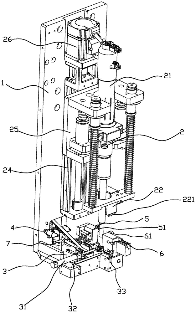
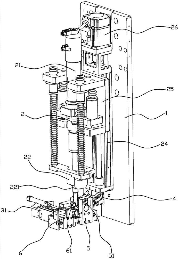
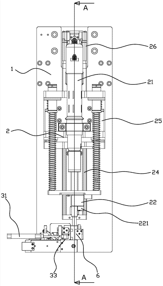
[0028] refer to Figure 1-12 , a novel screwing device, comprising a main mounting plate 1, on which a screwing assembly 2 is installed, and the screwing assembly 2 includes a screw gun 21 and a slope surface on both sides thereof 221 of the lower pressing block 22, the inside of the screw gun 21 is provided with a buffer spring 23, the lower part of the main mounting plate 1 is fixedly connected with the bottom mounting plate 3, and the bottom mounting plate 3 is directly or indirectly provided with a screw delivery assembly 4 , the first elastic slider assembly 5 and the second elastic slider assembly 6, the first elastic slider assembly 5 and the second elastic slider assembly 6 are respectively provided with slope surfaces 221 which are matched to the two sides of the above-mentioned lower pressing block 22 The first pulley 51 and the second pulley 61, the second screw slider assembly 6 is also provided with a screw recess 60 for moving the screw.

[0029] The bottom moun...


PUM


Abstract

The invention discloses a novel screw hitting device. The novel screw hitting device comprises a main installing plate. A screw hitting assembly is installed on the main installing plate and comprises a screw gun and a lower pressing block, wherein slopes are arranged on the two sides of the lower pressing block. A buffer spring is arranged inside the screw gun, the lower portion of the main installing plate is fixedly connected with a bottom installing plate, a screw conveying assembly, a first elastic sliding block assembly and a second elastic sliding block assembly are directly or indirectly arranged on the bottom installing plate, the first elastic sliding block assembly and the second elastic sliding block assembly are provided with a first pulley and a second pulley respectively, the first pulley and the second pulley are matched with the slopes on the two sides of the lower pressing block, and a screw concave position for screws to move is arranged on the second screw sliding block assembly. In the working process, the novel screw hitting device has the advantages of being short in consumed time, high in working efficiency and the like, and an existing screw hitting device does not have the advantages.

Description

technical field [0001] The invention relates to a screw driving device, in particular to a novel screw driving device. Background technique [0002] Existing a kind of screw driving device comprises a screw gun, and the suction nozzle of screw gun sucks screw from a station earlier, and then whole device moves to second station, and screw gun beats screw in predetermined position again. This kind of screw driving device has to repeat the above process every time a screw is driven, which takes a long time and has low work efficiency; in addition, when the screw gun is close to the screw, it is necessary to prevent the screw gun from colliding violently with the screw and damage the equipment. , The screw gun needs to approach the screw at a slow and low speed during the process, and needs to pause and wait, which leads to a lot of time-consuming work of this type of screw driving device, and it is difficult to achieve efficient work. Contents of the invention [0003] In o...

Claims


Application Information

Patent Timeline
IPC IPC(8): B23P19/06
CPCB23P19/06B25B23/04
Inventor 张松岭赵盛宇田亮郭卫军黄世生
Owner SHENZHEN HYMSON LASER INTELLIGENT EQUIP CO LTD
Why Eureka
Try Eureka