Novel front and rear frame hinged structure for loaders

A technology of a loader and a rear frame, applied in the field of machinery, can solve the problems of high cost, poor manufacturability, complex frame structure, etc., and achieve the effects of simplified manufacturing process, low cost and small turning radius

Inactive Publication Date: 2014-05-14
QINGDAO LUDA PROJECT MACHINE MFR
View PDF0 Cites 6 Cited by
  • Summary
  • Abstract
  • Description
  • Claims
  • Application Information

AI Technical Summary

Problems solved by technology

This kind of frame structure is complex, the manufacturability is not good, and the cost is relatively high

Method used


Image

  • Novel front and rear frame hinged structure for loaders
  • Novel front and rear frame hinged structure for loaders
  • Novel front and rear frame hinged structure for loaders

Examples


Embodiment Construction

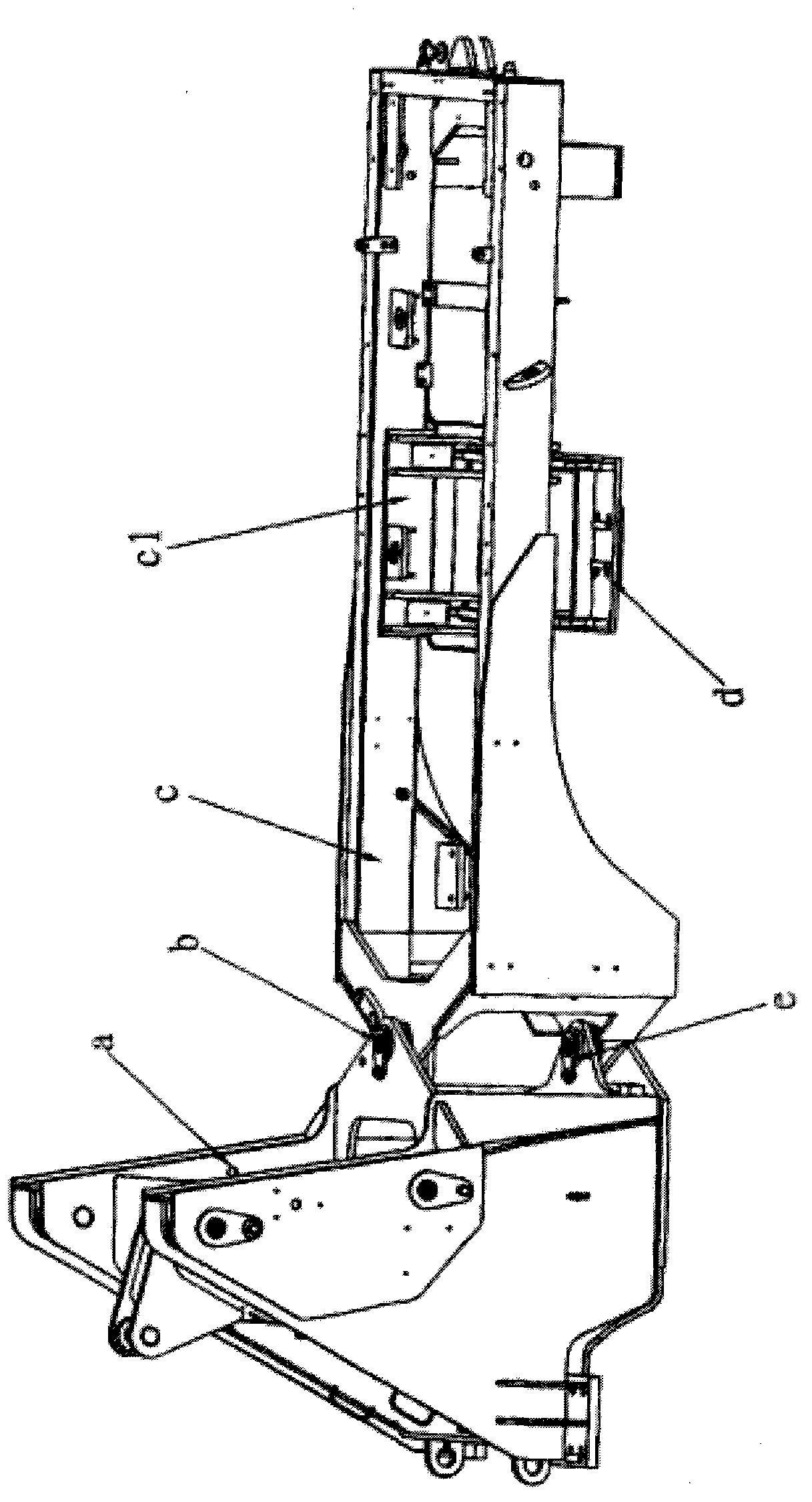
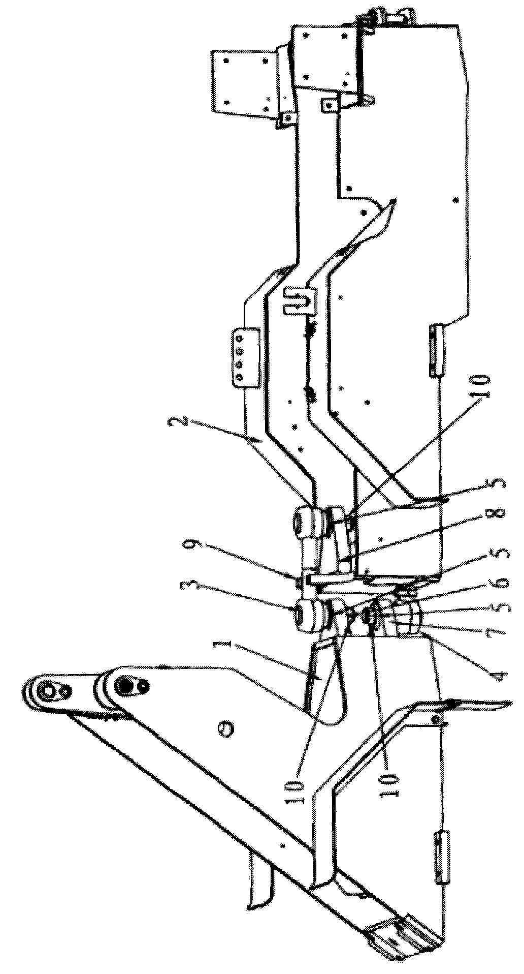
[0016] Such as figure 1 As shown, the present invention is a novel loader front and rear frame hinged structure, which includes a front frame 1, a rear frame 2, an upper rod ball 3, a lower rod ball 4, a taper sleeve 5, and a front upper hinge plate 6. , the front lower hinged plate 7, the rear hinged puller 8 and the limiting plate 9.

[0017] The front frame 1 is connected with the rear frame 2 through the upper link ball 3 and the lower link ball 4 .

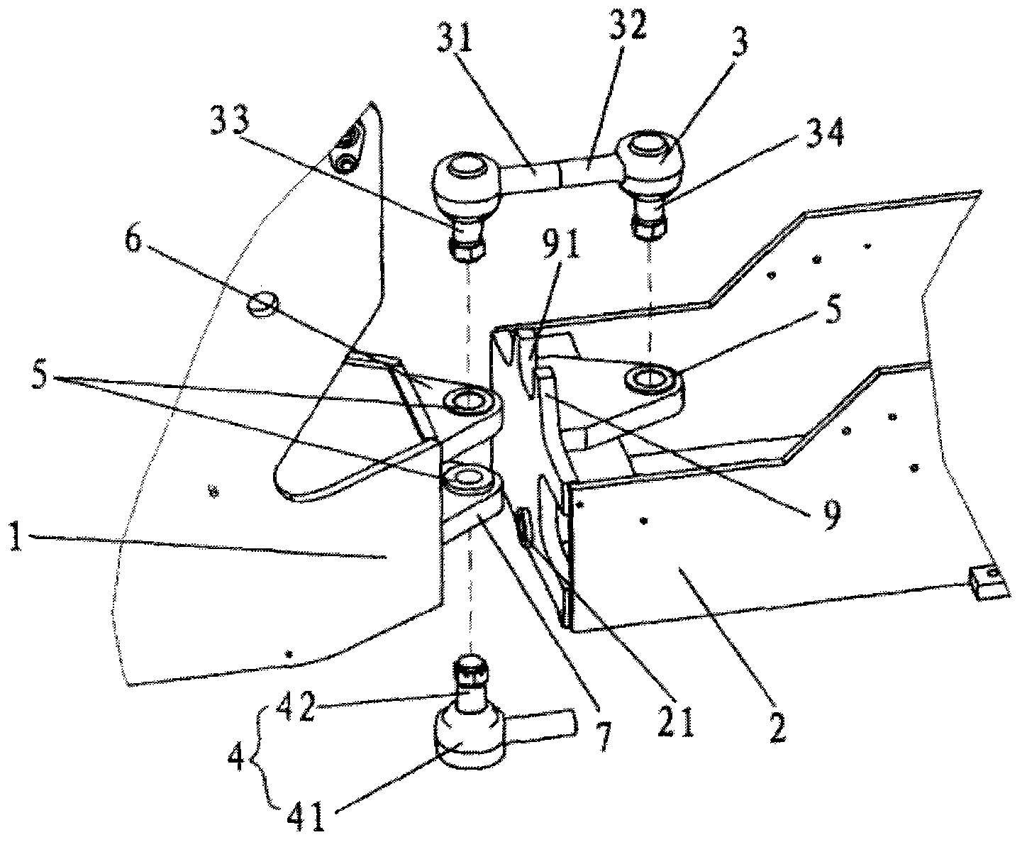
[0018] Such as Figure 4 As shown, the pull down rod head 4 is composed of a swing rod 41 and a pin shaft 42 . The inner end of the swing rod 41 is rotatably socketed on the top of the pin shaft 42, which is connected by a ball joint and has a self-lubricating structure inside. The free end of the swing rod 41 and the free end of the pin shaft 42 intersect perpendicularly.

[0019] Such as image 3 As shown, the pull-up rod head 3 is composed of two swing rods 31 , 32 and two pin shafts 33 , 34 . The inner ends of the tw...


PUM


Abstract

The invention discloses a novel front and rear frame hinged structure for loaders. The front and rear frame hinged structure comprises a front frame, a rear frame, an upper tie rod ball and a lower tie rod ball. The front frame and the rear frame are connected through the upper tie rod ball and the lower tie rod ball. Since the upper tie rod ball and the lower tie rod ball are connected between the front frame and the rear frame and are respectively connected through taper sleeves fixed on the front frame and the rear frame, taper surface cooperation can be realized, and the swinging range of the front frame and the rear frame can be limited through a limit board. The novel front and rear frame hinged structure has the advantages of simple structure, simplified manufacturing technique, low cost, good frame barrier through performance, large steering angle, small turning radius, capability of working within a narrow space and the like, thereby being suitable for being applied to small-sized loaders.

Description

technical field [0001] The invention belongs to the field of machinery, and in particular relates to a loader, in particular to a novel front and rear frame hinge structure of the loader. Background technique [0002] Such as figure 1 As shown, the existing small loader hinge structure is mainly composed of front frame a, upper hinge pin b, rear frame c, swing frame d, lower hinge pin e; front frame a and rear frame c are formed by The upper hinge pin shaft b is connected with the lower hinge pin shaft e, so that the relative left and right swing of the vehicle frame can be realized. The frame c1 is connected by a pin shaft. It is connected through the intermediate hinge frame on the front and rear frames. The upper and lower hinges are respectively assembled with pin shafts and bearings. The steering of the frame is realized through the intermediate hinge. The obstacle-crossing swing of the frame needs to be connected to the swing of the rear frame. rack to achieve. Thi...

Claims


Application Information

Patent Timeline
Patent Type & Authority Applications(China)
IPC IPC(8): B60D1/167B62D53/00
Inventor 付文君傅稼浩刘浩
Owner QINGDAO LUDA PROJECT MACHINE MFR
Why Eureka
Try Eureka