A steering wheel damper

A steering wheel and damper technology, which is applied to the steering control and handwheels installed on the car, can solve the problems of friction wear, high manufacturing cost, and large volume of the steering wheel damper, and achieve simple production and processing and small volume. Effect

Active Publication Date: 2015-10-28
长春和成汽车零部件有限公司
View PDF6 Cites 0 Cited by
  • Summary
  • Abstract
  • Description
  • Claims
  • Application Information

AI Technical Summary

Problems solved by technology

[0003] The steering wheel damper in the prior art has a large volume and high manufacturing cost, and the simple damper generally uses the friction force between the friction object and the rotating shaft to provide damping. After a long time of use, the friction object wears out, the damping force decreases, and the damping cannot be achieved. adjust

Method used


Image

  • A steering wheel damper
  • A steering wheel damper
  • A steering wheel damper

Examples


Embodiment 1

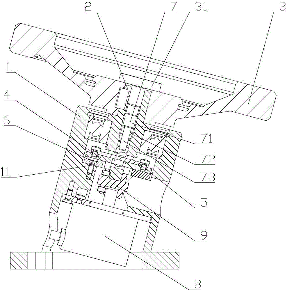
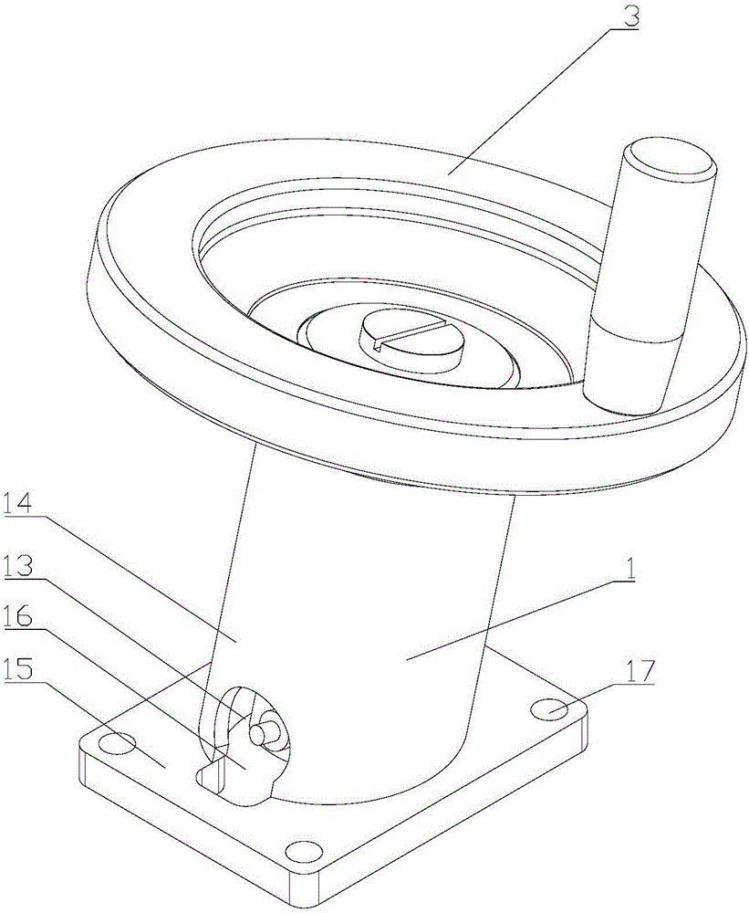
[0031] refer to figure 1 , image 3 As shown, a steering wheel damper provided by the present invention includes a hollow support base 1, a rotating shaft 2 passing through the support base 1, the rotating shaft 2 and the support base 1 can be connected through a bearing, and fixed with a circlip, A steering wheel 3 or an industrial handwheel etc. are installed on the rotating shaft 2, a step surface 11 is provided in the support seat 1, a static friction plate 4 is installed on the step surface 11, and a guide hole 21 is arranged on the rotating shaft 2 radially, the guide hole 21 It can be a waist-shaped hole or a rectangular hole. A mounting block 5 that can move axially along the rotating shaft 2 is perforated in the guide hole 21. The mounting block 5 is connected with a set of dynamic friction plates 6 that are arranged on the rotating shaft 2. The rotating shaft 2 The central position is also provided with a first installation hole 22 communicating with the guide hole ...

Embodiment 2

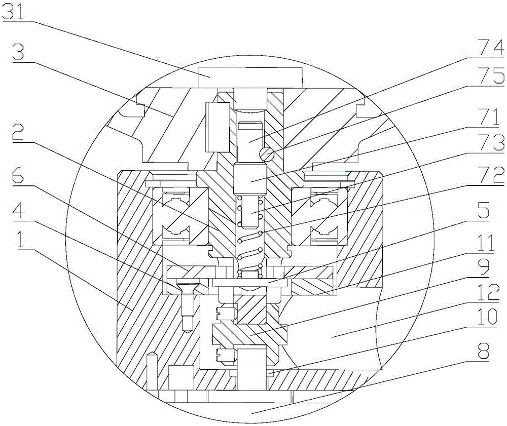
[0038] refer to figure 2 , Figure 10 As shown, the difference between this embodiment and Embodiment 1 is that a gear 74 is integrally provided on the top of the compression screw 71, and a second mounting hole 24 is provided at a position opposite to the gear on the rotating shaft 2, and a second mounting hole 24 is provided on the steering wheel 3 with the second gear. The position opposite to the mounting hole 24 is provided with an operation hole. A worm 75 is arranged in the second mounting hole 24. The worm 75 can only rotate in the rotating shaft 2. The end of the worm 75 is provided with a groove for rotating the worm 75. The groove can be a cross cut or a straight cut 76, which is used to facilitate the rotation of the screwdriver. Utilize the rotating worm 75 to drive the gear 74 to rotate, and finally drive the compression screw 71 to rotate and compress the dynamic friction plate 6. When it is necessary to adjust the internal friction damping, only need to use a...


PUM


Abstract

The invention discloses a damper of a steering wheel. The damper of the steering wheel comprises a hollow supporting base, a rotating shaft arranged in the supporting base in a penetrating mode, and the steering wheel installed on the rotating shaft, wherein a step face is arranged in the supporting base, a static friction sheet is installed on the step face, the rotating shaft is provided with a guiding hole in the radial direction, a mounting block capable of moving in the axial direction of the rotating shaft is arranged in the guiding hole in a penetrating mode, the mounting block is connected with a dynamic friction sheet arranged on the rotating shaft in a sleeved mode, a first mounting hole communicated with the guiding hole is further formed in the center of the rotating shaft, and a pressing mounting block is arranged in the first mounting hole to serve as a pressing device for making the dynamic friction sheet and the static friction sheet pressed to each other. According to the damper of the steering wheel, the static friction sheet is installed in the supporting base, the mounting block connected with the dynamic friction sheet is arranged in the rotating shaft, the mounting block and the dynamic friction sheet can move in the guiding hole in the axial direction of the rotating shaft, the pressing device for making the dynamic friction sheet and the static friction sheet pressed to each other is further arranged in the rotating shaft, and therefore the damper of the steering wheel is easy to produce and machine and small in size and further has the advantages that friction and damping can be adjusted freely.

Description

technical field [0001] The invention relates to the technical field of dampers, in particular to a steering wheel damper. Background technique [0002] The steering wheel damper is used to provide damping when the steering wheel is turned. On the one hand, it prevents the steering wheel from turning when it is subjected to a slight steering force. On the other hand, it is used to provide damping for manual operation to increase the comfort of operation. It is especially widely used in electric power steering. [0003] The steering wheel damper in the prior art has a large volume and high manufacturing cost, and the simple damper generally uses the friction force between the friction object and the rotating shaft to provide damping. After a long time of use, the friction object wears out, the damping force decreases, and the damping cannot be achieved. adjust. Contents of the invention [0004] The invention mainly solves the technical problems existing in the prior art, ...

Claims


Application Information

Patent Timeline
Patent Type & Authority Patents(China)
IPC IPC(8): B62D1/04
Inventor 毛秀惠
Owner 长春和成汽车零部件有限公司
Why Eureka
Try Eureka