Underground space building pile body construction method of and underground space building structure

A technology for underground space and building structures, applied in underwater structures, buildings, infrastructure engineering, etc., can solve problems such as long construction period, increased construction cost, increased construction cost, etc., to reduce the number of piles, enhance the resistance The effect of tensile crack resistance

Active Publication Date: 2014-05-14
JIANGXI JIYE SCI & TECH
View PDF6 Cites 1 Cited by
  • Summary
  • Abstract
  • Description
  • Claims
  • Application Information

AI Technical Summary

Problems solved by technology

[0003] However, a large increase in the number of conventional piles will lead to a long construction period and increase the construction cost. If the number of steel bars inside the pile is i

Method used


Image

  • Underground space building pile body construction method of and underground space building structure
  • Underground space building pile body construction method of and underground space building structure
  • Underground space building pile body construction method of and underground space building structure

Examples


Embodiment 1

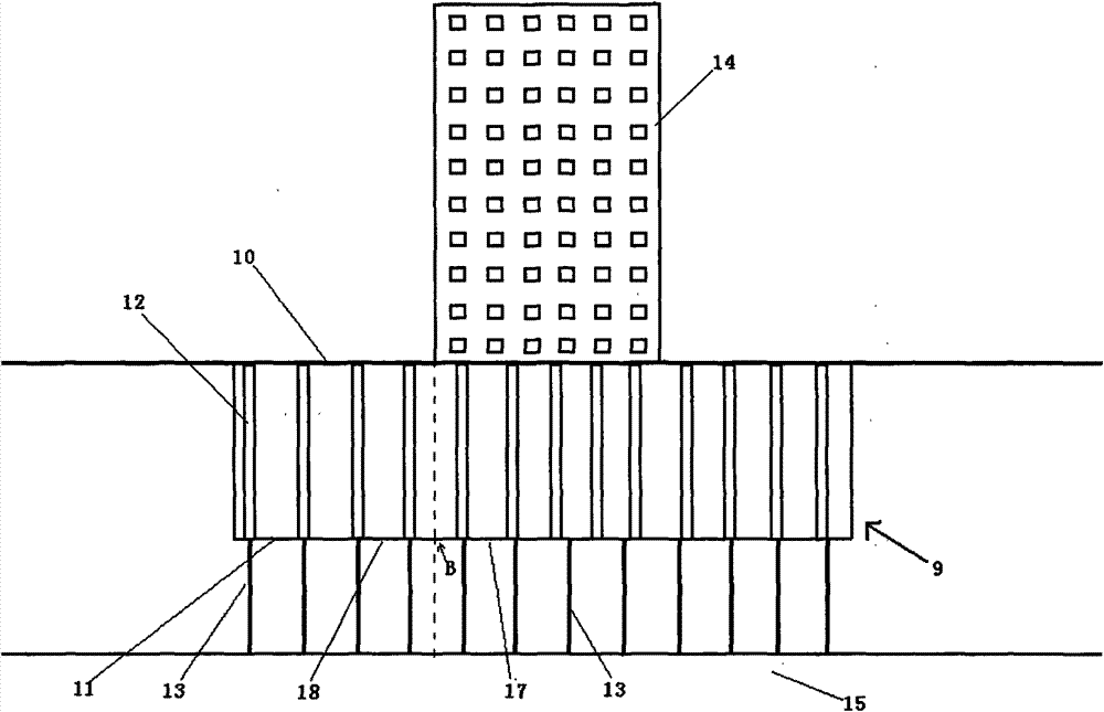
[0037] The building pile body construction method of the underground space of the present invention, wherein, such as figure 2 As shown, the underground space 13 includes a space bottom 11 as a building foundation and a space top 10 connected to the ground, and the space bottom 11 has at least a first part 17 that bears heavier pressure and a second part that bears lighter pressure 18;

[0038] The difference between the first force difference between the buoyancy force and pressure experienced by the second part 18 and the second force difference between the buoyancy force and pressure force experienced by the first part 17 is greater than the maximum bending resistance at point B of the junction of the two force;

[0039] Below the first part 17, a first pile group 13 for supporting and fixing the first part 17 is arranged, the first pile group can be a conventional pile group, and in the second part 18 The second pile group 16 for supporting and fixing the second part 18...

Embodiment 2

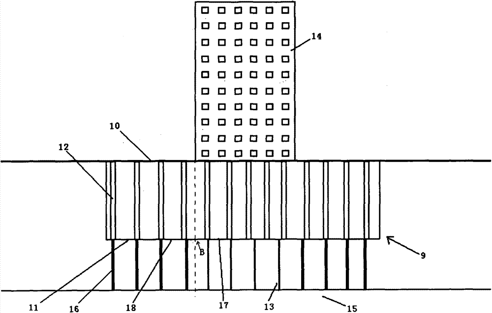
[0053] An underground space building structure adopting the construction method of Embodiment 1, comprising:

[0054] As the space bottom 11 of the building foundation and the space top 10 connected to the ground, the space top 10 has at least a first part 17 that bears a heavier pressure and a second part 18 that bears a lighter pressure; wherein the second part is subjected to The difference between the first force difference between the buoyancy force and the pressure force and the second force difference between the buoyancy force and the pressure force experienced by the first part is greater than the maximum bending resistance force of the junction of the two parts;

[0055] It also includes a first pile group 13 and a second pile group 16, which are respectively arranged vertically below the first part 17 and the second part 18, and are respectively connected to the first part 17 and the second part. 18 is supported and fixed, so as to ensure that the force difference b...


PUM


Abstract

The invention discloses an underground space building pile body construction method. An underground space comprises a space bottom serving as the foundation of a building and a space top connected with the ground, wherein the space bottom is at least provided with a first part used for bearing high pressure and a second part used for bearing low pressure, the difference value between first force difference between the buoyancy force and pressure borne by the second part and second force difference between the buoyancy force and pressure borne by the first part is larger than the largest breaking-resistant strength of the joint part of the first part and the second part, a first pile body set used for supporting and fixing the first part is arranged below the first part, a second pile body set used for supporting and fixing the second part is arranged below the second part, and then the difference between the buoyancy force and pressure borne by the second part is smaller than the largest breaking-resistant strength and the largest tensile resistance of the second pile body set.

Description

technical field [0001] The invention relates to a building construction method and a building structure, in particular to a building pile construction method for an underground space and an underground space building structure. Background technique [0002] At present, with the development of economy and society, more and more high-rise buildings appear in our cities. However, with the increase in the number of buildings in the city, the available space is becoming more and more scarce. Because of this, the underground space The development and utilization of has been paid more and more attention. like figure 1 As shown, the common underground space 9 is located directly below the high-rise building 14, and has a relatively deep longitudinal space. One end of the pile extending into the soil supports and fixes the bottom of the space, and the other end goes deep into the ground to support on the rock formation 15, while the top of the space carrying buildings or other obje...

Claims


Application Information

Patent Timeline
IPC IPC(8): E02D29/045E02D27/12E02D27/14E02D5/58
Inventor 刘献刚付豫楹熊小林
Owner JIANGXI JIYE SCI & TECH
Why Eureka
Try Eureka