A replaceable energy-dissipating steel plate composite slotted shear wall

A shear wall and replacement technology, which is applied to walls, building components, and earthquake resistance, can solve problems such as poor energy dissipation capacity and reduced bearing capacity, so as to make up for poor energy dissipation capacity, improve dissipation capacity, increase stiffness and load bearing capacity force effect

Active Publication Date: 2015-10-28
ZHIXING S&T
View PDF10 Cites 0 Cited by
  • Summary
  • Abstract
  • Description
  • Claims
  • Application Information

AI Technical Summary

Problems solved by technology

Although the ductility of the shear wall with vertical seams is improved, it has the disadvantages of reduced bearing capacity and poor energy dissipation capacity

Method used


Image

  • A replaceable energy-dissipating steel plate composite slotted shear wall
  • A replaceable energy-dissipating steel plate composite slotted shear wall
  • A replaceable energy-dissipating steel plate composite slotted shear wall

Examples


Embodiment 1

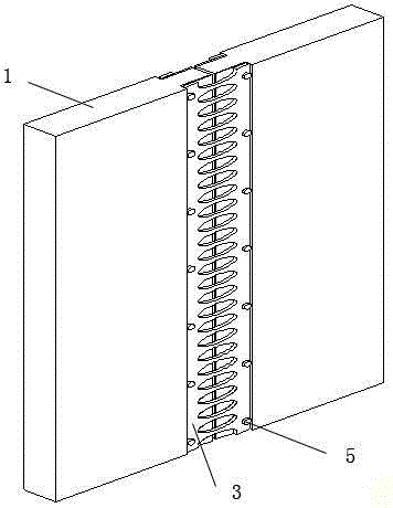
[0026] Such as figure 1 and 4 As shown, a replaceable energy-dissipating steel plate composite slotted shear wall is used to improve the energy dissipation and earthquake resistance of building structures, including shear wall 1, reinforced restraint steel plate 2, energy-dissipating steel plate 3 and threaded sleeve 4 .

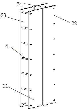
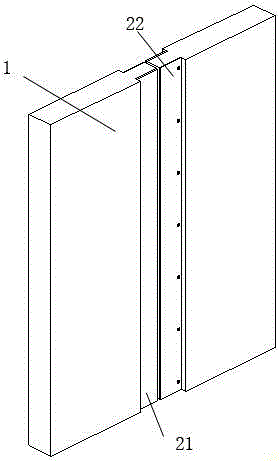
[0027] The shear wall 1 is vertically provided with through joints, and the reinforced restraint steel plates 2 are used to improve the rigidity and bearing capacity of the shear wall 1 and increase the replaceability, including the inner and outer two joints respectively arranged in the local area of ​​the shear wall 1. The first reinforced constrained steel plate 21, the second reinforced constrained steel plate 22, the third reinforced constrained steel plate 23, and the fourth reinforced constrained steel plate 24 are respectively poured and connected with the shear walls 1 on both sides of the joint.

[0028] The energy-dissipating steel plate 3 is us...

Embodiment 2

[0035]The rest are the same as in Example 1, except that the local wall thickness of the shear wall 1 on both sides of the vertical joint is smaller than the thickness of the normal shear wall, and the thickness difference of the shear wall on one side is 25 mm; There are eight steel plates, which are respectively connected to the shear walls on both sides of the joint and connected by pouring; the width of the joint is set to 22mm, and the joint is filled with a layer of cork material; the energy-dissipating steel plate is a soft steel plate with low yield , There are round holes on the soft steel plate.

Embodiment 3

[0037] The rest are the same as in Embodiment 1, the difference is that the local wall thickness of the shear wall 1 on both sides of the vertical joint is smaller than the thickness of the normal shear wall, and the thickness difference of the shear wall on one side is 28mm; The width is set to 25mm, and the through seam is filled with a layer of viscoelastic material.

[0038] The beneficial effect of adopting the above technical scheme is: the composite slotted shear wall makes full use of the deformation on both sides of the vertical joints of the shear wall and the yield energy dissipation capacity of the energy-dissipating steel plate to improve the energy dissipation capacity of the entire structure. At the same time, the rigidity and bearing capacity of the slotted shear wall are improved by arranging reinforced restraint steel plates on the inner and outer walls of the shear wall with vertical joints. Reinforced restraint steel plates are installed on the inner and ou...


PUM


Abstract

The invention discloses a combination slit shear wall with replaceable energy dissipation steel plates. The combination slit shear wall comprises a shear wall provided with a straight joint in the vertical direction, reinforcement constraint steel plates, the energy dissipation steel plates and threaded sleeves, wherein the reinforcement constraint steel plates are arranged on walls on the two sides of the straight joint and connected with the shear wall on the two sides of the straight joint in a casting mode. The energy dissipation steel plates are arranged on the outer sides of the reinforcement constraint steel plates and used for fixedly connecting the reinforcement constraint steel plates on the same side. The thread sleeves are used for fixedly connecting the energy dissipation steel plates with the reinforcement constraint steel plates and forming a casting frame with the reinforcement constraint steel plates. By the utilization of deformation of the two sides of the straight joint of the slit shear wall, the yield energy dissipation capacity of the energy dissipation steel plates is brought into full play, so that the energy dissipation and seismic resistant capacity of a building structure are greatly improved, and the slit shear wall has the advantages of being convenient to construct, install, repair and replace after an earthquake and meeting the requirements for seismic resistance and reduction design and functionality of the building structure.

Description

technical field [0001] The invention relates to the field of anti-seismic and energy-dissipating vibration-reduction control of building structures, in particular to a replaceable energy-dissipating steel plate combined slotted shear wall. Background technique [0002] Due to the high rigidity of the reinforced concrete shear wall structure, the small lateral deformation under horizontal action, and the bearing capacity is easy to meet the requirements, it is widely used in the construction of taller high-rise buildings. In order to expand the application scope of the shear wall and improve the seismic performance of the shear wall, many scholars have made in-depth research on the shear wall structure. [0003] As early as the end of the 1960s, Professor Wu Tengqing of Japan proposed the design idea of ​​shear walls with vertical joints to improve the shortcomings of low ductility and poor seismic performance of shear wall structures. This kind of shear wall with slots is e...

Claims


Application Information

Patent Timeline
Patent Type & Authority Patents(China)
IPC IPC(8): E04B2/00E04B1/98
Inventor 欧进萍刘敏王建李惠
Owner ZHIXING S&T
Why Eureka
Try Eureka