
Electromagnetic diaphragm pump

A diaphragm pump, electromagnetic technology, applied in the direction of pumps, liquid displacement machinery, pumps with flexible working elements, etc., can solve the problems of pump performance degradation burrs, etc., to achieve the suppression of performance degradation, reliable isolation, and uniform thickness Effect

Active Publication Date: 2014-05-14
FUJIKURA COMPOSITES INC
View PDF7 Cites 18 Cited by
  • Summary
  • Abstract
  • Description
  • Claims
  • Application Information

AI Technical Summary

Problems solved by technology

Therefore, as mentioned above, problems such as a reduction in pump performance due to the widening of the gap between the electromagnets and the generation of burrs on the mating surface inside the partition cylindrical part cannot be solved.

Method used


Image

  • Electromagnetic diaphragm pump
  • Electromagnetic diaphragm pump
  • Electromagnetic diaphragm pump

Examples


Embodiment Construction

[0033] Hereinafter, embodiments for carrying out the present invention will be described in detail with reference to the drawings.

[0034] In addition, this invention is not limited to the form demonstrated below, In the range which does not deviate from a technical idea, various deformation|transformation can be implemented. In addition, in the attached drawings, for the sake of explanation, the scales of up, down, and left and right are sometimes shown exaggeratedly, and may differ from actual scales.

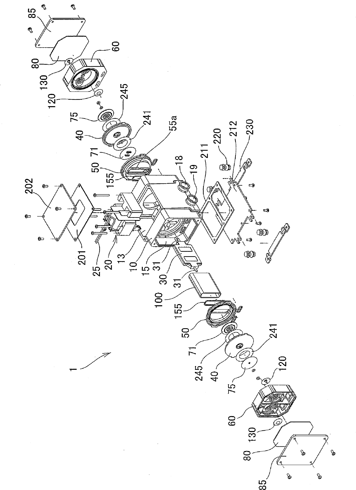
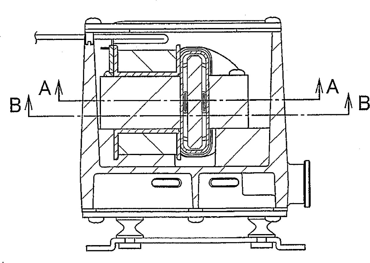
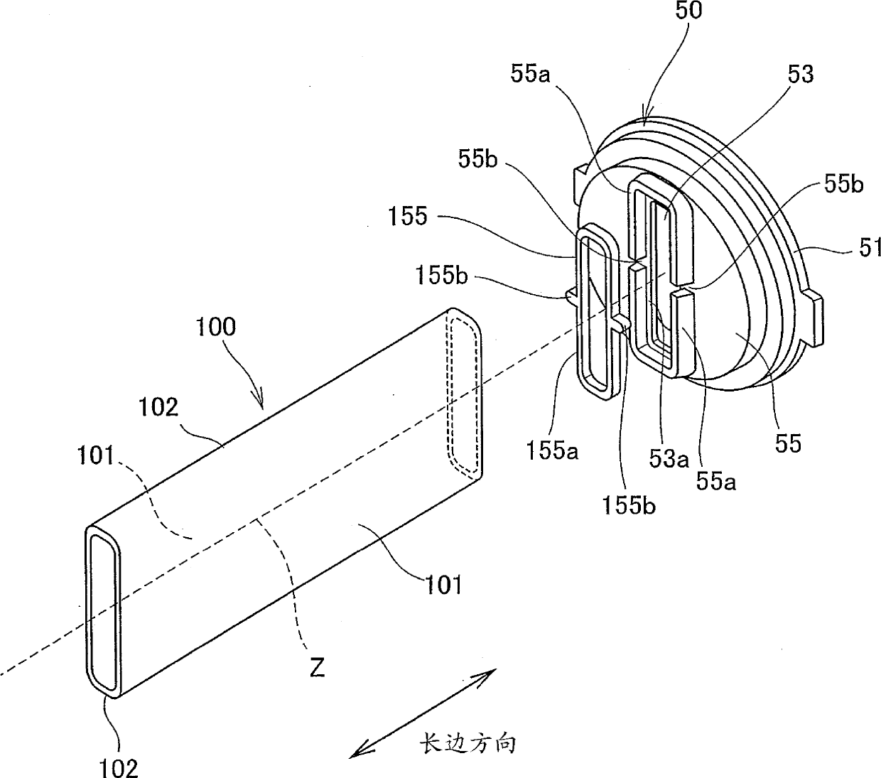
[0035] figure 1 It is a perspective view schematically showing the disassembled state of the electromagnetic diaphragm pump of the present invention into each main part, figure 2 It is a plan view showing the necessary parts of the main part of the electromagnetic diaphragm pump of the present invention in section, image 3 so figure 2 The section in the direction of the arrow II-II is a front view showing the essential parts of the main part of the electromagnetic diap...


PUM


Abstract

The invention belongs to an electromagnetic diaphragm pump. The pump comprises electromagnets; an oscillator vibrating along with changes of the polarity of the electromagnets; diaphragms arranged at the end portion of the oscillator; diaphragm stands and diaphragm holding portions that can clamp and fix the periphery of each diaphragm; and an oscillator cover covering the oscillator. A pair of inner separation chambers closer to the inside than the diaphragms is formed by means of the diaphragm stands and the diaphragms, such that the oscillator cover separated from the diaphragm stands can be installed in a way that the pair of inner separation chambers is communicated.

Description

technical field [0001] The present invention relates to, for example, an electromagnetic diaphragm pump for household fuel cells, and an electromagnetic diaphragm pump for pressure feeding fuel gas such as LPG. In particular, it relates to an electromagnetic diaphragm pump, which is equipped with a pump when the fluid is blown to the inside of the pump due to damage to the diaphragm. In the case of leakage, the leaked liquid cannot enter the current-carrying part of the isolation structure, and the isolation effect of the isolation structure can be reliably given in advance to prevent accidents caused by leakage in advance, and the performance degradation of the electromagnetic pump can be suppressed. . Background technique [0002] Conventionally, an electromagnetic diaphragm pump is known. As shown in the schematic top sectional view of FIG. Spit out (discharge). [0003] In such an electromagnetic diaphragm pump, generally, a pair of opposing diaphragms 520 are arranged...

Claims


Application Information

Patent Timeline
IPC IPC(8): F04B45/047
CPCF04B43/02F04B45/04
Inventor 中岛由晴
Owner FUJIKURA COMPOSITES INC
Learn More