Pumping equipment

A pumping equipment and pumping technology, applied in mechanical equipment, pump components, components of pumping devices for elastic fluids, etc., can solve the problem of reducing coaxiality, reducing the coaxiality of pumping units, Distortion and other problems, to achieve the effect of improving coaxiality accuracy and reliability

Active Publication Date: 2014-05-14
ZOOMLION HEAVY IND CO LTD
View PDF9 Cites 6 Cited by
  • Summary
  • Abstract
  • Description
  • Claims
  • Application Information

AI Technical Summary

Problems solved by technology

Same as the first method, when the two mounting pins on both sides of the water tank are not equal in height, it is easy to cause the pumping unit to be distorted; in addition, the water tank is hinged on the sub-frame 3 through the mounting pin 7, and the deformation of the sub-frame 3 And the vibration will still be completely transmitted to the water tank installation pin 7, reducing the coaxiality of the pumping unit; again, the hopper end is double-hinged suspension. However, the water tank end is fixed by the installation pin, so it cannot swing and move synchronously, and the pumping unit will be twisted and deformed, which will reduce the coaxiality and reduce the service life of key components such as pistons, oil cylinders and concrete cylinders.
[0007] In summary, none of the supporting and fixing structures of the pumping unit in the prior art can adapt to the size error and assembly error of the pumping unit components, which easily leads to the deformation of the pumping unit
It is also impossible to isolate the deformation and vibration of the subframe 3. The deformation and vibration of the subframe 3 will be directly transmitted to the pumping unit, which may also cause deformation of the pumping unit.

Method used


Image

  • Pumping equipment
  • Pumping equipment
  • Pumping equipment

Examples


Embodiment Construction

[0044] The present invention will be described in detail below with reference to the accompanying drawings and examples.

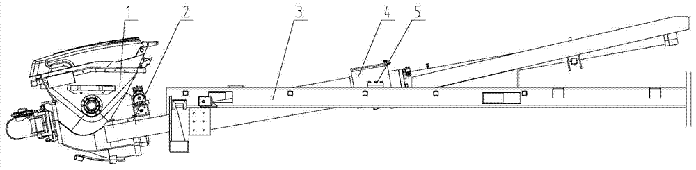
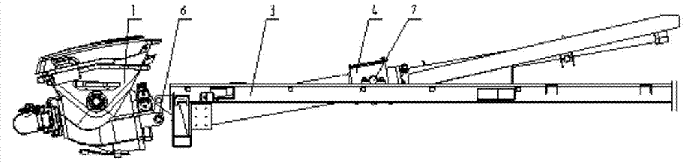
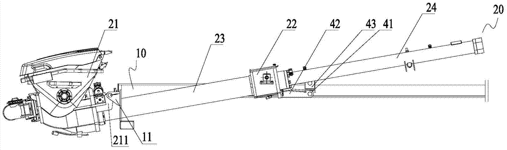
[0045] Such as Figure 4 and Figures 14 to 16As shown, the pumping device according to the present invention includes a frame 10 and a pumping unit 20 arranged on the frame 10. The pumping device also includes an elastic support arranged on the frame 10. The elastic support includes: at least two The first elastic support 44 is arranged on both sides of the pumping unit 20 to limit the lateral displacement of the pumping unit 20; the second elastic support 45; is arranged on the frame 10 and forms an elastic support to the bottom of the pumping unit 20, so as to Vibration of the pumping unit 20 up and down is restricted. According to the pumping device of the present invention, elastic supports are provided, and the elastic supports include at least two first elastic supports 44 that limit the lateral shaking of the pumping unit and second elastic suppo...


PUM


Abstract

The invention provides a set of pumping equipment. The pumping equipment comprises a rack and a pumping unit arranged on the rack. The pumping equipment further comprises elastic supports arranged on the rack, wherein the elastic supports comprise at least two first elastic supports and a second elastic support, the at least two first elastic supports are arranged on the two sides of the pumping unit so as to prevent the pumping unit from shaking laterally, and the second elastic support is arranged on the rack and elastically supports the lower portion of the pumping unit so as to prevent the pumping unit from shaking up and down. According to the pumping equipment, the elastic supports are arranged and comprise the at least two first elastic supports for preventing the pumping unit from shaking laterally and the second elastic support for preventing the pumping unit from shaking up and down, namely, the first elastic supports and the second elastic support are matched for use, buffering is formed for shaking and deformation in the vertical direction and the lateral direction, and therefore shaking and deformation of a frame are prevented from being directly transmitted to the pumping unit, the coaxiality accuracy of the pumping unit is improved, the service life of a piston, an oil cylinder, a concrete cylinder and other key parts is prolonged, and the reliability of the pumping unit is improved.

Description

technical field [0001] The invention relates to the field of pumping slurry materials such as concrete, in particular to a pumping device. Background technique [0002] In the prior art, the supporting and fixing structures of the pumping unit mainly include figure 1 and figure 2 Both are shown. Such as figure 1 As shown, the two sides of the hopper of the pumping unit 1 are connected to the sub-frame 3 through the hopper fixing bolts 2, and the water tank flaps are fixed on both sides of the water tank 4 of the pumping unit 1, and the water tank flaps are fixed on the auxiliary frame through the fixing bolts 5. On the water tank mounting seat on the vehicle frame 3. [0003] However, with this fixed connection method, since the water tank flange is welded on the water tank, its position and angle accuracy are low due to the influence of positioning accuracy and welding deformation, so that when the pumping unit 1 is installed, it is necessary to adjust the water tank m...

Claims


Application Information

Patent Timeline
Patent Type & Authority Applications(China)
IPC IPC(8): F04B53/00
Inventor 李铮徐建华
Owner ZOOMLION HEAVY IND CO LTD
Why Eureka
Try Eureka