Compressor

A compressor and compression mechanism technology, applied in the field of compressors, can solve the problems of compressor efficiency decrease, noise and power consumption increase, etc., so as to simplify the overall structure and cost, reduce the risk of leakage to the suction side, reduce residual The effect of void volume

Active Publication Date: 2014-05-14
EMERSON CLIMATE TECH (SUZHOU) CO LTD
View PDF9 Cites 10 Cited by
  • Summary
  • Abstract
  • Description
  • Claims
  • Application Information

AI Technical Summary

Problems solved by technology

[0003] When the compressor is stopped or unloaded, due to the pressure difference between the discharge side and the suction side of the compressor, the fluid on the discharge side tends to flow to the suction side, so the compression mechanism of the compressor may be blocked by this The reverse flow drives the fluid to move in the opposite direction, resulting in a decrease in the efficiency of the compressor and an increase in noise and power consumption

Method used


Image

  • Compressor
  • Compressor
  • Compressor

Examples


Embodiment Construction

[0026] The following description of preferred embodiments is exemplary only and in no way restricts the invention and its application or usage. The same reference numerals are used to denote the same components in the respective drawings, and thus the configurations of the same components will not be described repeatedly.

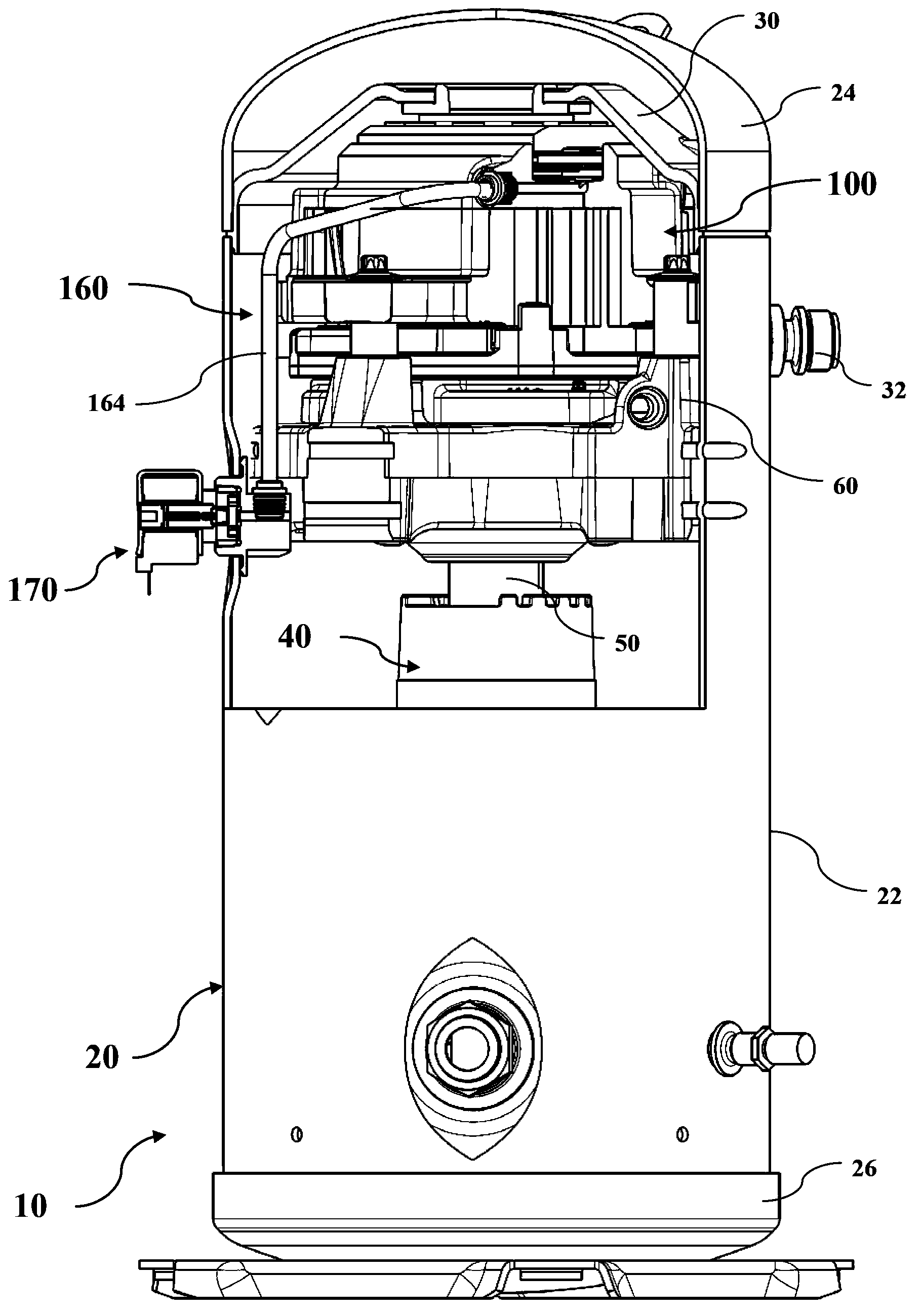
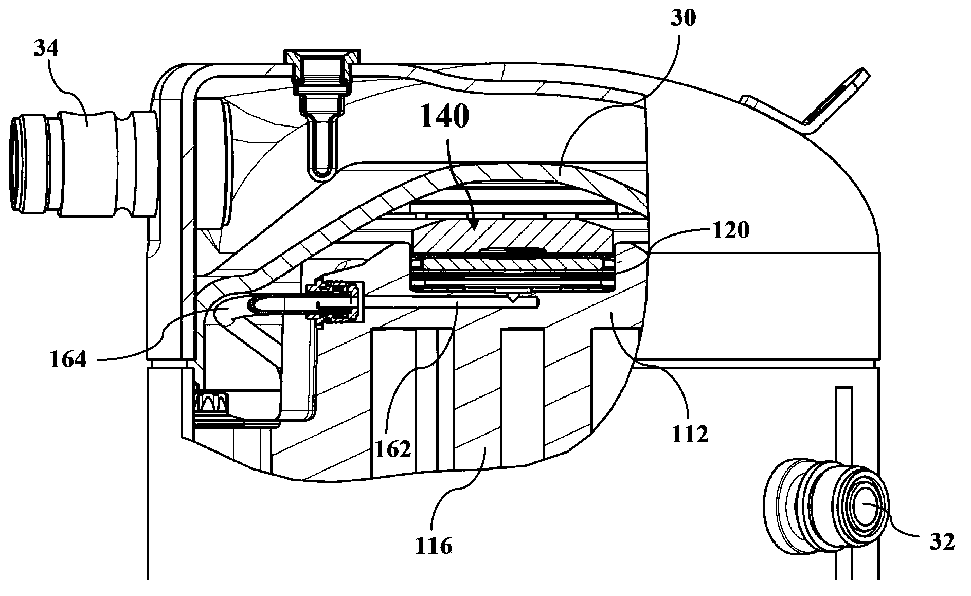
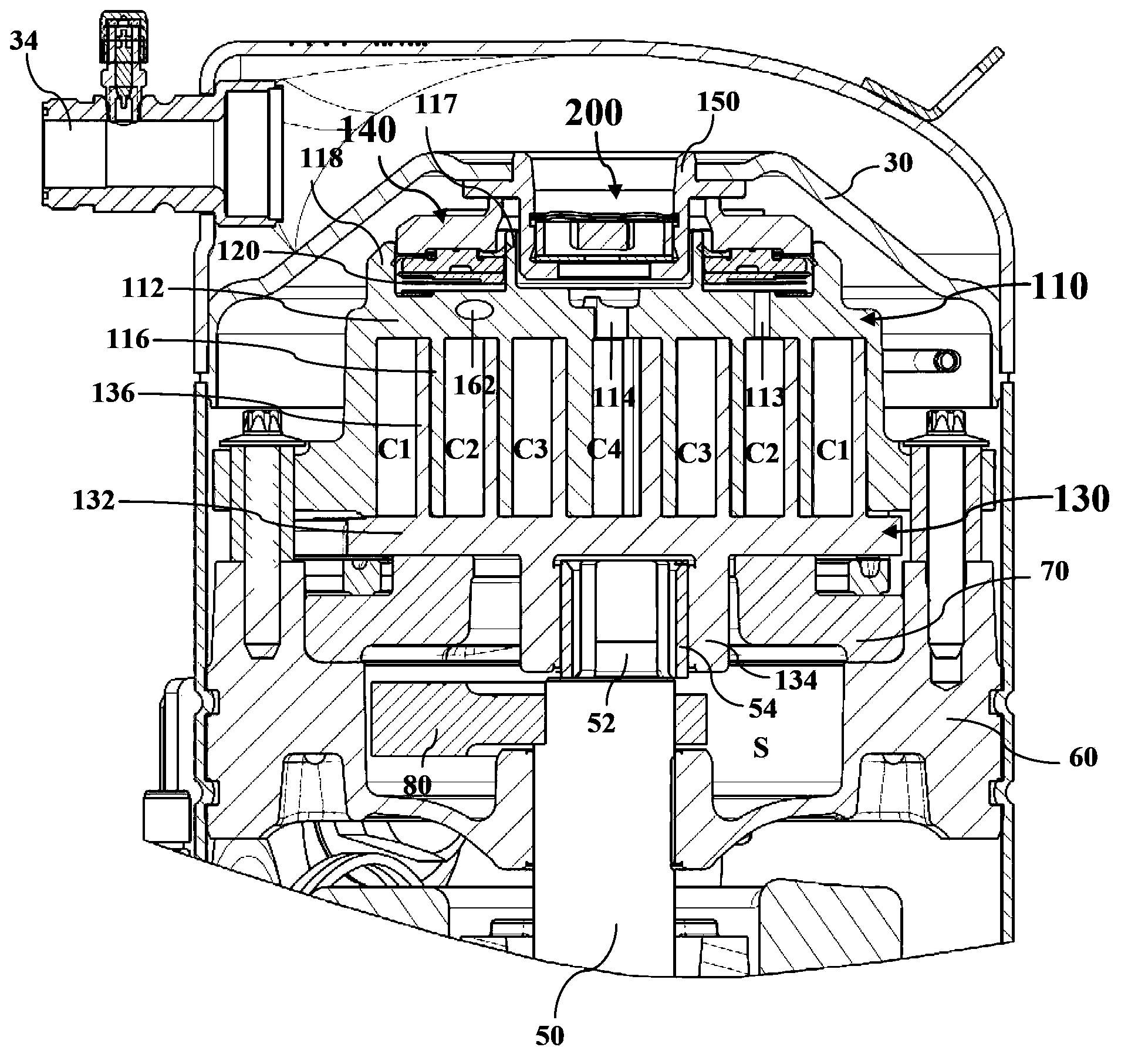
[0027] The following will refer to Figure 1-3 The basic configuration of the compressor according to the first embodiment of the present invention is described. Such as figure 1 As shown, compressor 10 includes a generally closed housing 20 . The housing 20 may be composed of a substantially cylindrical body portion 22 , a top cover 24 disposed at one end of the body portion 22 , and a bottom cover 26 disposed at the other end of the body portion 22 . A partition 30 is provided between the top cover 24 and the body portion 22 to partition the inner space of the housing 20 into a suction side and a discharge side. The space between the partition 30 and ...


PUM


Abstract

The invention relates to a compressor (10), comprising a shell (20), a separator plate (30) and a compressing mechanism (100), wherein the separator plate (30) divides the inner space of the shell (20) into a suction side and an exhaust side; the compressing mechanism (100) is arranged in the shell and compresses a fluid sucked in from the suction side and discharges the fluid to the exhaust side; and the separator plate (30) is internally provided with an opening (32) for communicating an exhaust opening (114) of the compressing mechanism (100) with the fluid of the exhaust side, and the opening (32) of the separator plate (30) is provided with a throttling valve for preventing or attenuating the fluid from flowing back to the suction side from the exhaust side. According to the compressor provided by the invention, the fluid of the exhaust side is effectively prevented from flowing back to the suction side, thereby increasing operation efficiency of the compressor.

Description

technical field [0001] The present invention relates to a compressor. Background technique [0002] The statements in this section merely provide background information related to the present disclosure and may not constitute prior art. [0003] When the compressor is stopped or unloaded, due to the pressure difference between the discharge side and the suction side of the compressor, the fluid on the discharge side tends to flow to the suction side, so the compression mechanism of the compressor may be blocked by this The reverse flow drives the compressor to move in the opposite direction, resulting in reduced compressor efficiency, increased noise, and increased power consumption. [0004] Therefore, there is a need for a compressor that prevents fluid backflow during shutdown or unloading. Contents of the invention [0005] It is an object of one or more embodiments of the present invention to provide a more efficient compressor. [0006] Another object of one or mo...

Claims


Application Information

Patent Timeline
Patent Type & Authority Applications(China)
IPC IPC(8): F04C29/12
Inventor 于英林韩艳春
Owner EMERSON CLIMATE TECH (SUZHOU) CO LTD
Why Eureka
Try Eureka