
Finned tube heat exchanger

A heat exchanger and finned tube technology, applied in the field of finned tube heat exchangers, can solve problems such as fin frosting, and achieve the effect of improving heat exchange performance

Inactive Publication Date: 2014-05-14
PANASONIC CORP
View PDF7 Cites 4 Cited by
  • Summary
  • Abstract
  • Description
  • Claims
  • Application Information

AI Technical Summary

Problems solved by technology

[0007] When the above-mentioned conventional finned tube heat exchanger is used, for example, in an outdoor unit of an air conditioner, especially during heating operation when the outside air is low temperature, it is easy to generate heat on the windward part of the fin 111. frost

Method used


Image

  • Finned tube heat exchanger
  • Finned tube heat exchanger
  • Finned tube heat exchanger

Examples


Embodiment approach )

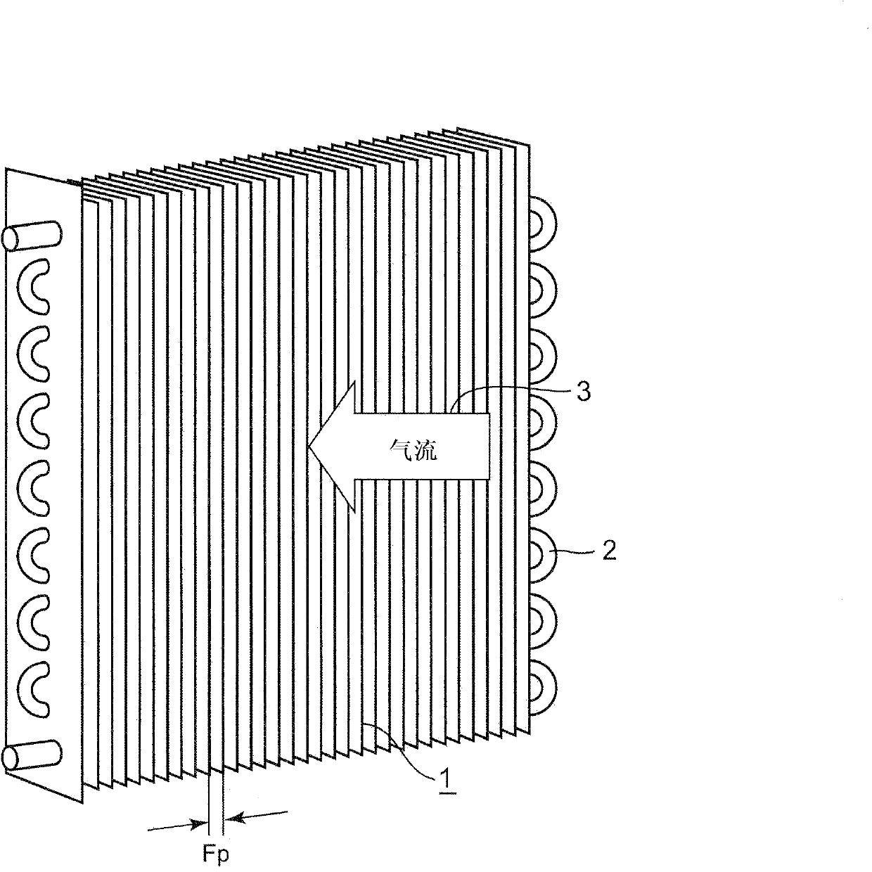
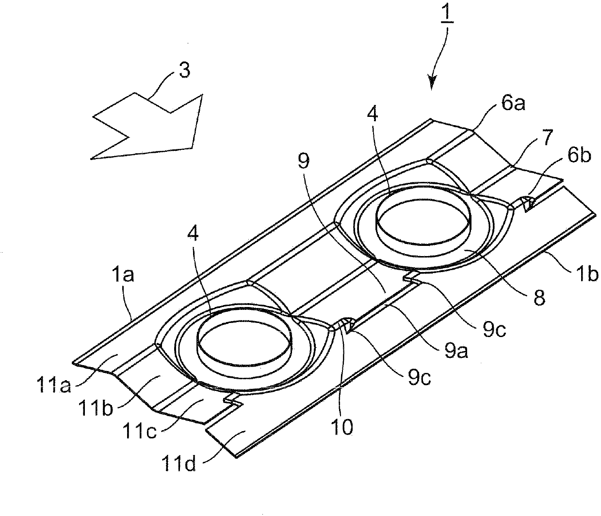
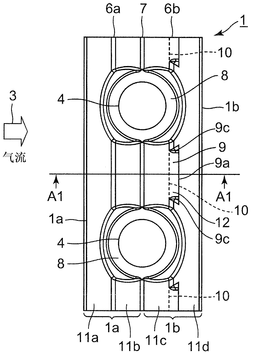
[0046] figure 1 It is a perspective view of the finned tube heat exchanger concerning embodiment of this invention. figure 2 yes figure 1 A partial perspective view of fins included in the shown finned tube heat exchanger. Figure 3A yes figure 2 A partial plan view of the fin shown. Figure 3B yes Figure 3A A1-A1 line sectional view. The finned tube heat exchanger according to the present embodiment is installed, for example, in outdoor units such as air conditioners, heat pump water heaters, and heat pump hot water heaters.

[0047] Such as figure 1 As shown, the finned tube heat exchanger of this embodiment includes: a plurality of fins 1 stacked at a distance Fp for forming the flow path of the airflow 3; Heat transfer tube 2.

[0048] Inside the heat transfer tube 2 , a fluid that exchanges heat with an air flow 3 such as air sent between the plurality of fins 1 by a blower (not shown) flows therethrough. Furthermore, if figure 1 As shown, a plurality of ...


PUM


Abstract

The invention provides a finned tube heat exchanger that is improved in heat exchange performance. The finned tube heat exchanger comprises multiple fins (1) laminated in a mutually spaced manner, and multiple heat transfer tubes (2) penetrating the multiple fins (1) in the lamination direction, wherein fluids for heat exchange of air flows flowing among the multiple fins (1) flow across the heat transfer tubes (2). Each fin (1) is provided with ripple-shaped portions alternatively appearing between peak portions (6a, 6b) and a valley portion (7) of air flows (3) in the flowing direction. In the flowing direction of the air flows (3), a ridge line (10) of one peak portion (6b) between two adjacent heat transfer tubes (2) in the plumb direction, positioned at a side lower than the central portion of each fin (1), is equipped with an air window (9).

Description

technical field [0001] The present invention relates to a finned tube heat exchanger for heat exchange of refrigerant. Background technique [0002] For a long time, such finned tube heat exchangers as Figure 8 What is shown includes: a plurality of fins 101 stacked at intervals; and a plurality of heat transfer tubes 102 provided to pass through the plurality of fins 101 in the stacking direction. [0003] In this finned tube heat exchanger, an air flow 103 such as air blown by a blower (not shown) flows between adjacent fins 101 , thereby interacting with the fluid flowing inside the heat transfer tubes 102 . heat exchange. [0004] As a finned tube heat exchanger having such a structure, it is disclosed, for example, in Patent Document 1 (Japanese Unexamined Patent Publication No. 2001-091101). [0005] Figure 9A It is a partial plan view of the fins included in the conventional fin-tube heat exchanger. Figure 9B yes Figure 9A A0-A0 line sectional view. Figure ...

Claims


Application Information

Patent Timeline
Patent Type & Authority Applications(China)
IPC IPC(8): F25B39/00F28F1/32F28F13/02
Inventor 广田正宣野间富之横山昭一木田琢己名越健二山本宪昭朔晦诚大城崇裕
Owner PANASONIC CORP
Learn More