Multi-working-mode gas flowmeter and gas flow measuring method

A technology of gas flowmeter and working mode, which is applied in fixed measuring chambers and movable measuring chambers, can solve problems such as low baking temperature, large measurement uncertainty, and difficulty in extending the lower limit of gas flowmeter flow, and achieve The effect of expanding the measuring range and facilitating measurement

Inactive Publication Date: 2014-05-14
LANZHOU INST OF PHYSICS CHINESE ACADEMY OF SPACE TECH
View PDF4 Cites 11 Cited by
  • Summary
  • Abstract
  • Description
  • Claims
  • Application Information

AI Technical Summary

Problems solved by technology

Since most of the gas micro flowmeters in the past have a single working mode, the measurement range is narrow and the measurement uncertainty is large, different devices are required to measure the gas micro flow in different ranges, and effective comparison cannot be carried out. The key parts of the flowmeter are made of non-metallic substances, which leads to low baking temperature, which makes the overall degassing of the gas micro-flowmeter insufficient. When measuring the gas flow, the wall is deflated, which makes it difficult to extend the lower limit of the flow of the gas flowmeter.

Method used


Image

  • Multi-working-mode gas flowmeter and gas flow measuring method
  • Multi-working-mode gas flowmeter and gas flow measuring method
  • Multi-working-mode gas flowmeter and gas flow measuring method

Examples


Embodiment 1

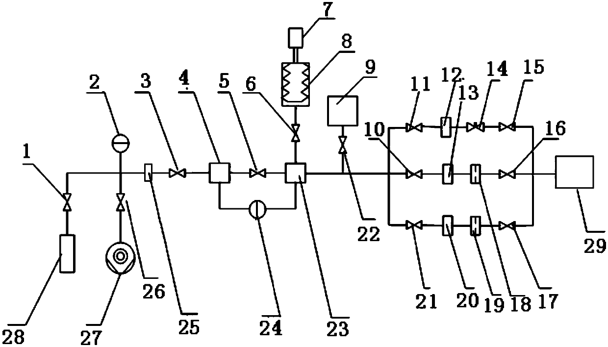
[0036] Step 1: evacuate the gas flowmeter to a preset vacuum degree;

[0037] Step 2: Open the second cut-off valve, open the valve on the first branch, close the valve on the second branch, and fill the gas flow meter with gas;

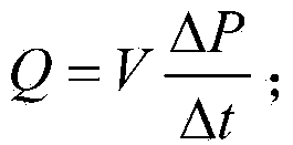
[0038] Step 3: After the air pressure in the reference chamber, comparison chamber and constant volume chamber in the gas flowmeter is stable, introduce the gas in the gas flowmeter into the calibration chamber, and then use the first pressure gauge to measure the preset time Compare the pressure change value in the inner chamber, and use the following formula to calculate the gas flow

[0039] Q = V ΔP Δt ; - - - ( 1 )

[0040] Wherein, Q is the gas flow rate; V is the total volume of the reference chamber, the comparison chamber, the constant volume chamber, the volume chamber on the fir...

Embodiment 2

[0044] Step 1: pumping the gas flowmeter to a preset vacuum degree, and heating and baking the gas flowmeter to a preset temperature during the pumping process;

[0045] Step 2: Open the second cut-off valve, close the valve on the first branch, open the valve on the second branch, and fill the gas flow meter with gas;

[0046] Step 3: After the air pressure in the reference chamber, the comparison chamber and the constant volume chamber in the gas flowmeter is stabilized, the gas in the gas flowmeter is introduced into the calibration chamber through a small-diameter connecting pipe, and the gas in the gas flowmeter is passed through the first pressure gauge. Measure the gas pressure in the gas flow meter, and use the following formula to calculate the gas flow at the small-diameter connecting pipe

[0047] Q'=cp; (2)

[0048] Among them, c is the flow conductance of the gas; p is the gas pressure in the gas flowmeter; Q' is the gas flow rate of the small-diameter connecting...

Embodiment 3

[0053] Step 1: pumping the gas flowmeter to a preset vacuum degree, and heating and baking the gas flowmeter to a preset temperature during the pumping process;

[0054] Step 2: Open the second cut-off valve, close the valve on the first branch, open the valve on the second branch, and fill the gas flow meter with gas;

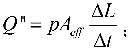
[0055] Step 3: After the air pressure in the reference chamber, the comparison chamber and the variable capacity chamber in the multi-working mode gas flowmeter is stable, introduce the gas in the multi-working mode gas flowmeter into the calibration chamber through a small-caliber connecting pipe , close the third shut-off valve and then stop filling gas into the multi-working mode gas flow meter, measure the pressure difference between the reference chamber and the comparison chamber through the differential pressure manometer, and open the first cut-off valve The valve introduces the gas in the comparison chamber into the variable volume chamber, and drives...


PUM


Abstract

The invention relates to a multi-working-mode gas flowmeter and a gas flow measuring method. The multi-working-mode gas flowmeter comprises first pressure gauges, a reference chamber, a comparison chamber, at least two parallel branches, a calibrating chamber, a variable-volume chamber, a fixed-volume chamber, a third stop valve and a differential pressure gauge, wherein the first pressure gauges are serially connected to one another; each branch is provided with a volume chamber; the volume chamber of at least one branch is connected with a small-diameter connecting pipe; the variable-volume chamber is connected with the comparison chamber and has a moving structure capable of adjusting the volume of the volume chamber; the fixed-volume chamber is connected between the comparison chamber and a flow distributing circuit; the third stop valve is connected between the reference chamber and the comparison chamber; and the differential pressure gauge is connected with the reference chamber and the comparison chamber. The gas flow measuring method comprises the following steps of vacuumizing the gas flowmeter; filling gas in the flowmeter; measuring the pressure of the filled gas; and measuring and calculating the flow of the gas. The flow distributing circuit comprises at least two parallel branches, a stop valve is arranged between every two parts, different parts can be combined, so that the gas flowmeter can measure the flow of gas in a plurality of working modes, and the range ability is improved.

Description

technical field [0001] The invention relates to the field of gas flow measurement, in particular to a multi-working mode gas flow meter and a gas flow measurement method. Background technique [0002] A gas flow meter is a device for measuring and providing gas micro-flow. It is the basis for establishing gas micro-flow measurement and calibration standard devices. Accurate measurement of gas flow is of great significance. With the development of my country's aerospace industry, the development of manned spacecraft, launch vehicle and other technologies has expanded the range of gas micro-flow measurement and calibration, the extension of the minimum gas flow measurement and calibration lower limit, and the accuracy of gas micro-flow measurement instruments, Reliability requirements are getting higher and higher, so it is necessary to develop a gas microflowmeter with smaller measurement uncertainty, wide measurement range, and lower measurement limit. Since most of the gas ...

Claims


Application Information

Patent Timeline
IPC IPC(8): G01F11/12G01F11/36
Inventor 赵澜成永军张伟文张瑞芳杨长青盛学民刘珈彤
Owner LANZHOU INST OF PHYSICS CHINESE ACADEMY OF SPACE TECH
Why Eureka
Try Eureka