
A detection device and detection method

A detection device and a technology to be detected, applied in the direction of color/spectral characteristic measurement, optical test flaws/defects, etc., can solve problems such as sensors not being able to perceive, and achieve accurate detection results

Active Publication Date: 2017-06-06
BEIJING BOE DISPLAY TECH CO LTD +1
View PDF8 Cites 0 Cited by
  • Summary
  • Abstract
  • Description
  • Claims
  • Application Information

AI Technical Summary

Problems solved by technology

In addition, when using sensors for inspection, no matter how many sensors there are, there will be blind spots that the sensors cannot sense during the inspection process.

Method used


Image

  • A detection device and detection method
  • A detection device and detection method
  • A detection device and detection method

Examples


Embodiment Construction

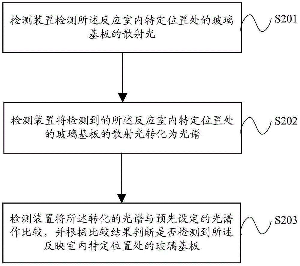
[0043] Embodiments of the present invention provide a detection device and a method for detecting whether a glass substrate in a reaction chamber is damaged by using the detection device, so as to conveniently and accurately detect the damage of the glass substrate in the reaction chamber in actual production.

[0044] A detailed introduction of the technical solutions provided by specific embodiments of the present invention is given below.

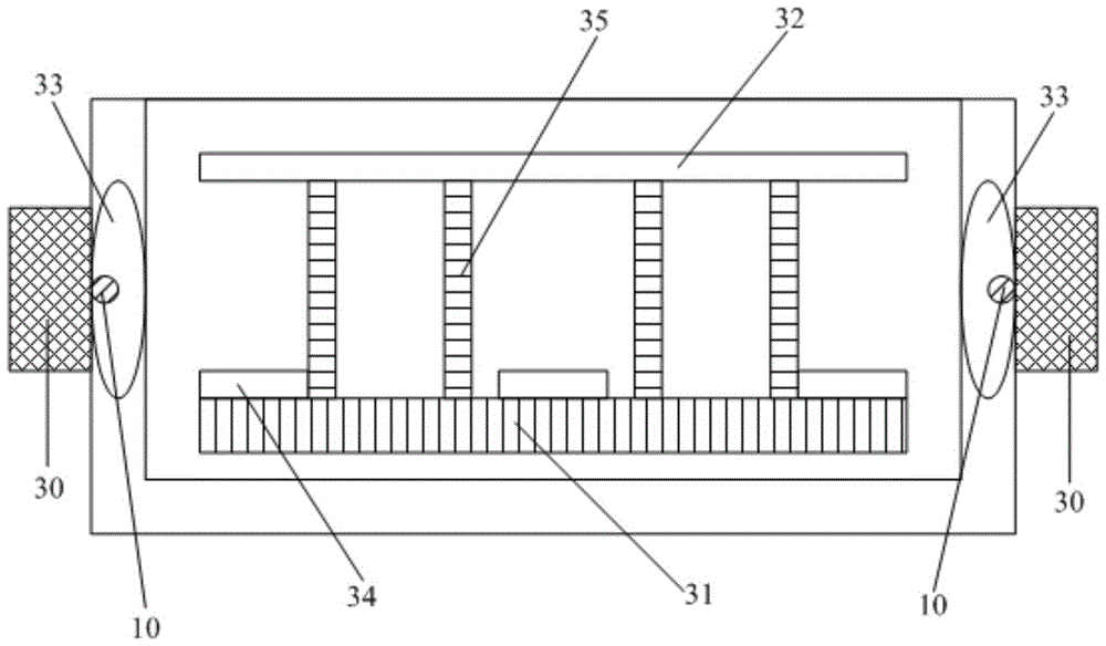
[0045] The specific embodiment of the present invention is specifically described by taking the reaction chamber of a dry engraving machine as an example. Certainly, the specific embodiment of the present invention is not limited to the reaction chamber of a dry engraving machine, and may also be a reaction chamber of other production equipment, such as a chamber for coating The reaction chamber of the magnetron sputtering equipment.

[0046]The current dry engraving machine usually uses a transfer chamber shared by multiple reaction cha...


PUM


Abstract

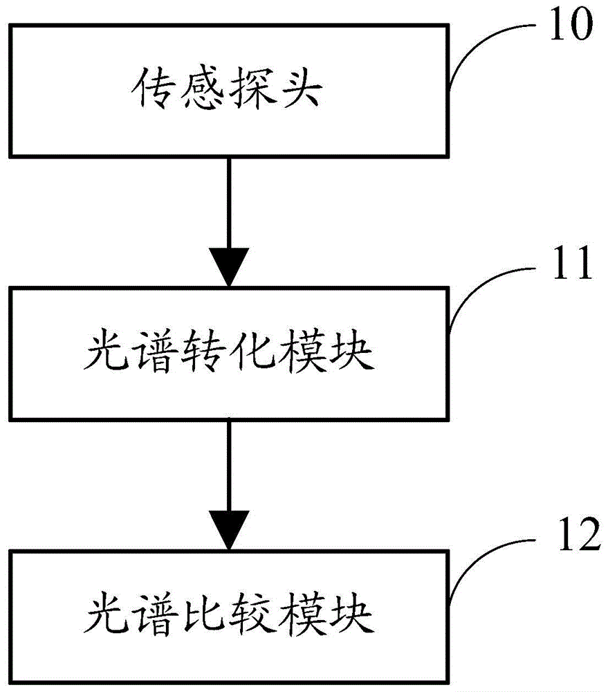
The invention discloses a detection device and a method for detecting that whether a glass substrate in a reaction chamber is damaged or not by using the detection device, and the detection device and the detection method are used for conveniently and accurately detecting the damage situation of the glass substrate in the reaction chamber in practical production. The device comprises a sensing probe, a spectrum conversion module, and a spectrum comparison module, wherein the sensing probe is used for receiving scattered light of a detected object; the spectrum conversion module is used for converting the scattered light, received by the sensing probe, into spectrum; the spectrum comparison module is used for comparing the converted spectrum with a preset spectrum, and judging whether the detected object is detected or not according to the comparison result.

Description

technical field [0001] The invention relates to the field of display technology, in particular to a detection device and a detection method. Background technique [0002] The prior art discloses a breakage detection device that detects breakage of an edge portion of a glass substrate moving on a production line of a flat panel display device using an optical sensor. The device uses two lower or upper sensors arranged at the position where the glass substrate is to be moved to identify the glass substrate and send out a signal when the glass substrate passes through; the controller is electrically connected to the at least two sensors and receives the at least two sensors. The respective signals of the two sensors. When the glass substrate passes the upper part or the lower part of the at least two sensors, read the received signals from the at least two sensors respectively, and determine the time required for the glass substrate to pass through each sensor completely, or w...

Claims


Application Information

Patent Timeline
Patent Type & Authority Patents(China)
IPC IPC(8): G01N21/25G01N21/88
Inventor 张定涛袁明吴成龙郑云友宋泳珍李伟
Owner BEIJING BOE DISPLAY TECH CO LTD
Learn More