
Economical concrete carbonization test box

A technology of carbonization test chamber and concrete, which is applied in the field of test chambers, can solve the problems of increasing the air pressure in the chamber, large loss of carbon dioxide, complex structure of the chamber, etc., and achieves small loss of carbon dioxide, small loss of carbon dioxide, and good gas uniformity Effect

Inactive Publication Date: 2014-05-14
郭健
View PDF3 Cites 4 Cited by
  • Summary
  • Abstract
  • Description
  • Claims
  • Application Information

AI Technical Summary

Problems solved by technology

"An Intelligent Concrete Carbonation Test Chamber" authorized on April 3, 2002, the patent number is ZL01244866.4, introduced an intelligent concrete carbonation test chamber that can automatically adjust the carbon dioxide concentration. Gives a good solution, but does not mention how to reduce CO2 loss
The "pull-out concrete carbonation test chamber" authorized on August 10, 2011, with the patent number ZL201020677534.5, proposed a chamber structure that reduces carbon dioxide loss, but the chamber structure is too complicated and fails to fundamentally The reason is that there are serious defects in the design of the current concrete carbonation test chamber: the process of increasing the concentration of carbon dioxide gas entering the chamber is the process of increasing the air pressure in the chamber and squeezing out excess air, which results in the following Contradiction: In order to reduce the loss of carbon dioxide, the airtightness of the box should be done well, but at the same time, in order to squeeze out excess air, the box cannot be completely sealed
In the process of expelling excess air at the beginning of the test, a large amount of carbon dioxide is also discharged; due to the poor airtightness of the box, carbon dioxide leakage is accompanied by the carbonization test all the time, so the existing concrete carbonation test chamber causes a huge loss of carbon dioxide, very poor economy

Method used


Image

  • Economical concrete carbonization test box
  • Economical concrete carbonization test box

Examples


Embodiment Construction

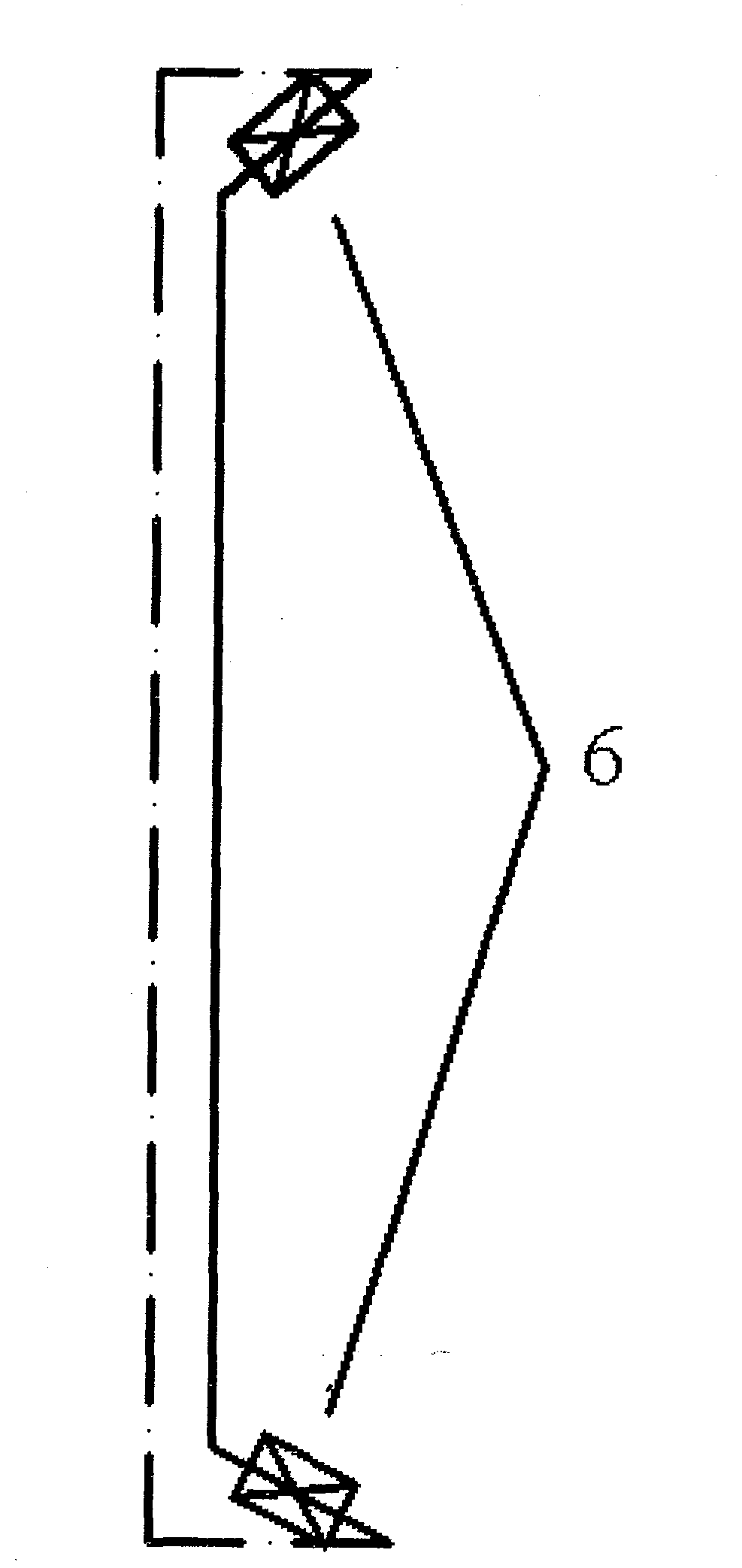
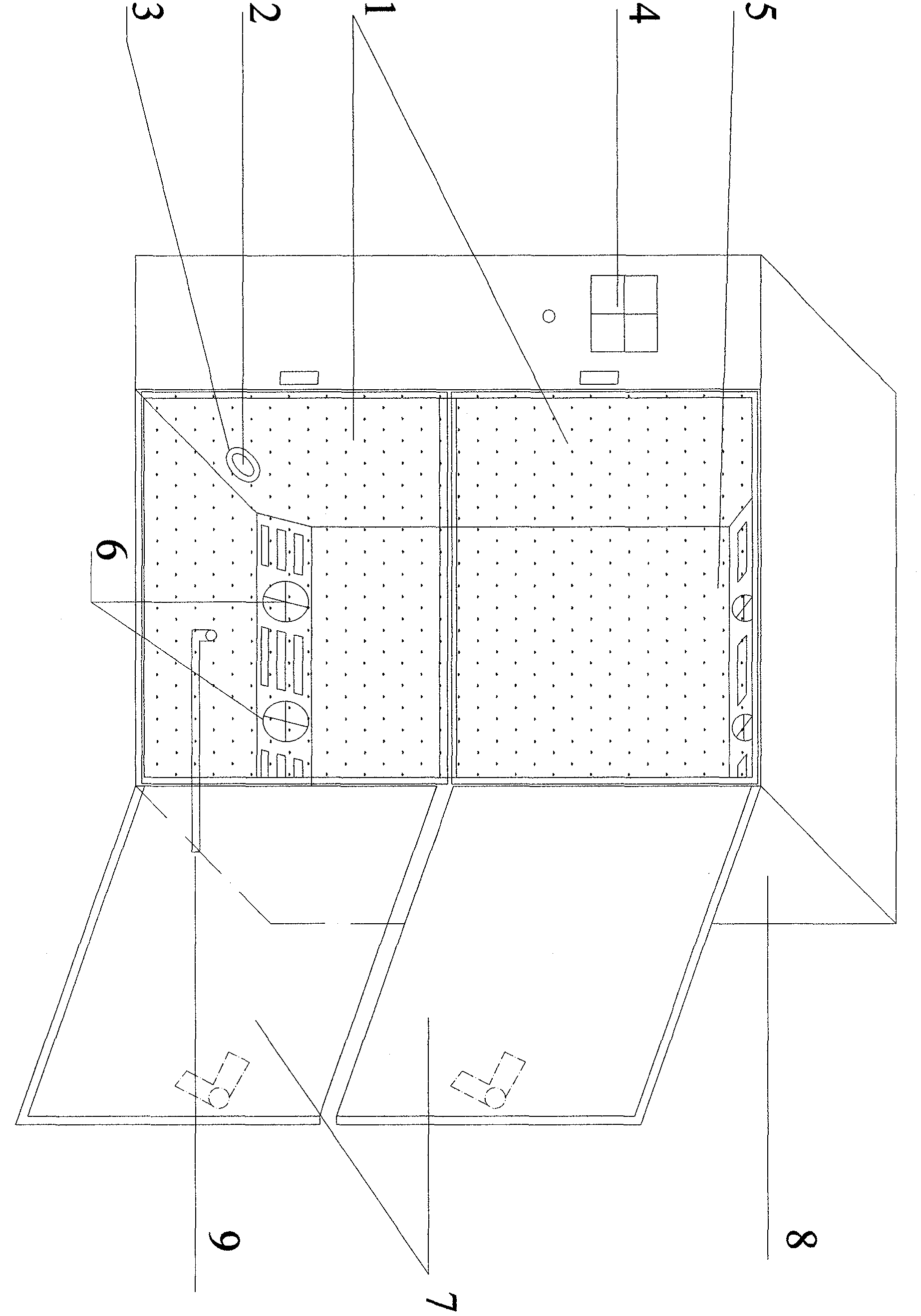
[0016] see figure 1 , an economical concrete carbonation test chamber, mainly includes a temperature and humidity control system, a carbon dioxide concentration control system and a chamber. Since the temperature and humidity control system and the carbon dioxide concentration control system are the same as those of the prior art, they are not shown in the accompanying drawings, and will not be repeated here. Described box body is made up of box door 7 and box cabinet 8, and described box body is provided with controller 4, and described box body is provided with gas circulation device 5, and described box body is provided with exhaust fan 2 and The valve 3 is provided with a switchable drain 9 at the bottom, and a door curtain 1 is provided outside the door frame of the cabinet 8 . The gas circulation device 5 is provided with an auxiliary fan 6 . The exhaust fan 2 , the valve 3 and the auxiliary fan 6 are connected with the control system 4 .

[0017] First, the door 7 an...


PUM


Abstract

The invention discloses an economical concrete carbonization test box which comprises a box body, and is characterized in that door curtains are arranged on the outer side of a door frame of the box body; an exhaust fan and a valve are arranged at the bottom of the box body; each door curtain is positioned between the door frame and each door of the box body; a gas circulation device is arranged in the box body and is provided with an auxiliary fan; the exhaust fan, the valve and the auxiliary fan are connected with a control system; an openable water drainage opening is formed in the bottom of the box body. According to the economical concrete carbonization test box, under a condition of ensuring that the carbon dioxide concentration meets a test requirement, the airtightness of the box body is improved; the gas uniformity in the box is high, the carbon dioxide loss is small, and the economical property is high.

Description

technical field [0001] The invention relates to a test box, in particular to test equipment for detecting the degree of carbonation of concrete under the action of certain temperature, humidity and carbon dioxide concentration. Background technique [0002] Concrete carbonation test chamber is a special equipment for concrete carbonation test. Carbonation of concrete refers to a kind of chemical corrosion suffered by concrete. CO in the air 2 The gas penetrates into the concrete and reacts chemically with its alkaline substances to generate carbonate and water, and the process of reducing the alkalinity of concrete is called concrete carbonation, also known as neutralization. Carbonation is basically harmless to plain concrete, but for reinforced concrete, carbonation will reduce the alkalinity of concrete and increase the number of hydrogen ions in the concrete pore solution, thus weakening the protective effect of concrete on steel bars and increasing the strength of ste...

Claims


Application Information

Patent Timeline
IPC IPC(8): G01N33/38
Inventor 郭健
Owner 郭健
Learn More