Supporting machine table

A machine and support pin technology, which is applied in optics, instruments, electrical components, etc., can solve the problem of particles generated by support pins and pin grooves, and achieve the effects of improving yield, reducing particles, and reducing the generation of particles

Inactive Publication Date: 2014-05-14
BEIJING BOE DISPLAY TECH CO LTD +1
View PDF6 Cites 8 Cited by
  • Summary
  • Abstract
  • Description
  • Claims
  • Application Information

AI Technical Summary

Problems solved by technology

[0006] The present invention aims to overcome the problem of particles generated by sliding friction between the support pin and the pin groove of the gluing machine in the prior art, thereby preventing Shell Mura from occurring on the liquid crystal panel.

Method used


Image

  • Supporting machine table
  • Supporting machine table
  • Supporting machine table

Examples


Embodiment Construction

[0023] The specific embodiments of the present invention will be described in further detail below with reference to the accompanying drawings and embodiments. The following examples are intended to illustrate the present invention, but not to limit the scope of the present invention.

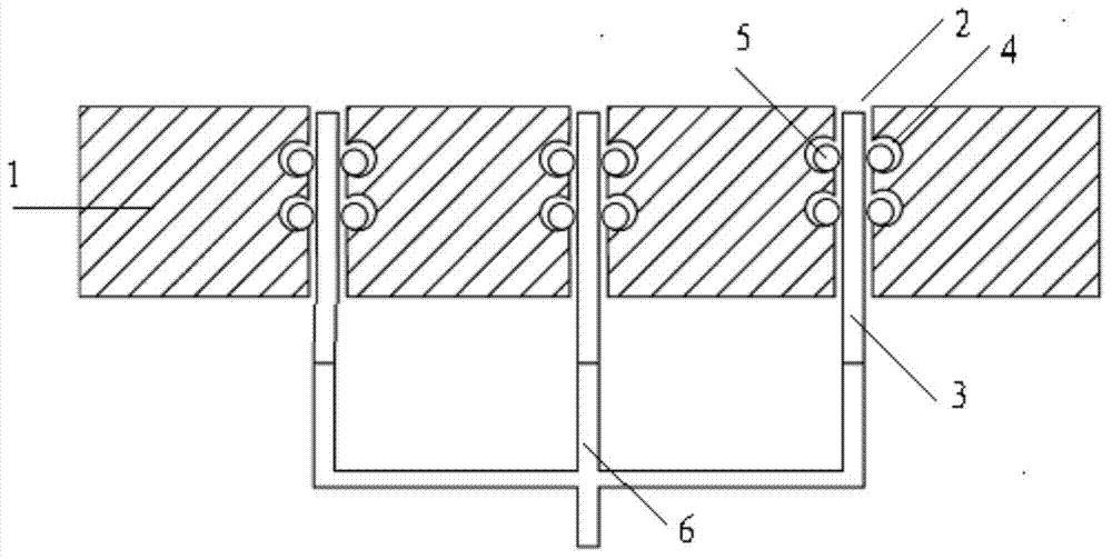
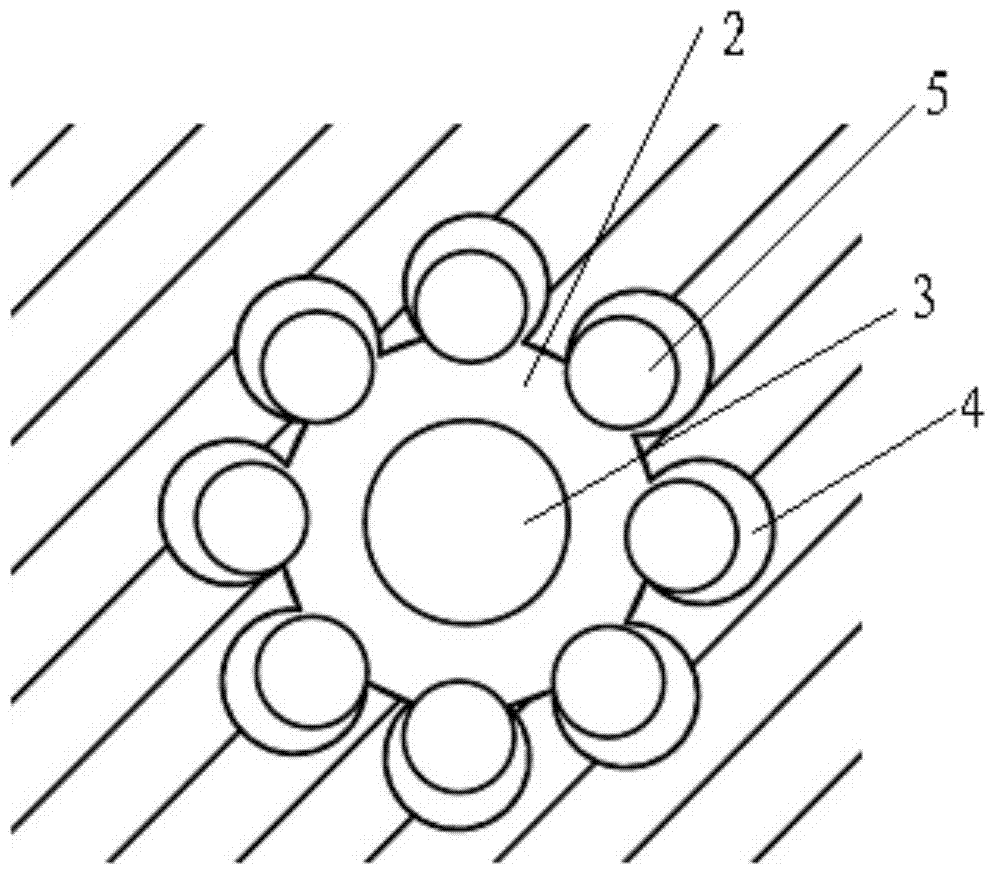
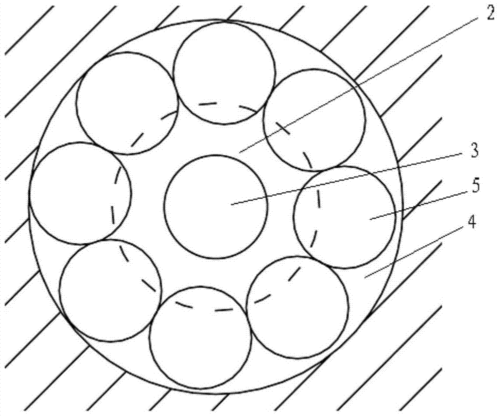
[0024] figure 1 It is a partial cross-sectional view of the support machine in the vertical direction of the present invention, figure 2 It is a partial cross-sectional view of a pin hole of the supporting machine of the present invention in the horizontal direction at its annular groove. The surface of the support machine 1 is horizontal for placing the substrate. Compared with the prior art, the improvement of the present invention lies in the structure of the pin hole, so the structure of the pin hole is mainly described below.

[0025] The support machine 1 includes at least one pin hole 2, the pin hole 2 accommodates a support pin 3 that can move up and down, the hole wall of the pin h...


PUM


Abstract

The invention relates to a supporting machine table. The supporting machine table comprises a plurality of pin holes, supporting pins which can move up and down are accommodated in the pin holes, at least one groove is formed in the walls of the pin holes, balls are accommodated in the grooves, freely roll in the grooves, and located around the supporting pins accommodated in the pin holes, and each ball can roll in the corresponding groove and a part of each ball always protrudes out of the walls of the pin holes due to the shape and the size of the grooves. According to the supporting machine table, the balls are arranged in the pin holes, when the supporting pins are deflected or bent, sliding friction between the supporting pins and the walls of the pin holes is converted into rolling friction between the supporting pins and the balls, generated particles can be reduced, particles adsorbed on a liquid crystal display panel are greatly reduced, Shell Mura is prevented from generating in the liquid crystal display panel, and the yield of products is increased.

Description

technical field [0001] The invention relates to the technical field of liquid crystal display manufacturing, in particular to a support machine. Background technique [0002] The development of liquid crystal display technology has been quite mature so far, and the main competition of various panel companies is more and more inclined to increase the yield and reduce the cost. [0003] In the lithography (Array Photo) process of liquid crystal manufacturing, a linear coater (Linear Coater) is used for coating. In order to ensure the thickness of the photoresist film, the glass substrate (Glass) needs to be vacuum adsorbed on the coating machine (Coater Stage) and then Guaranteed to be stable. Generally, a pin groove running through the thickness direction is provided in the gluing machine table, and the lift pin is located in the pin hole, and the glass substrate is lifted up when picking and placing the glass substrate. [0004] As an important device for picking and placi...

Claims


Application Information

Patent Timeline
Patent Type & Authority Applications(China)
IPC IPC(8): G02F1/13
CPCG03F7/16G02F1/1303H01L21/68742
Inventor 李星火王涛王鹏丁振勇韩亚军陈国
Owner BEIJING BOE DISPLAY TECH CO LTD
Why Eureka
Try Eureka