Omnidirectional antenna

An omnidirectional antenna and director technology, which is applied in antennas, antenna unit combinations with different polarization directions, independent antenna unit combinations, etc., can solve problems such as communication quality degradation, poor signal quality, and incomplete antenna coverage directions. Achieve the effects of improving signal quality, reducing size, and improving user experience

Active Publication Date: 2014-05-14
KUANG CHI INST OF ADVANCED TECH
View PDF5 Cites 4 Cited by
  • Summary
  • Abstract
  • Description
  • Claims
  • Application Information

AI Technical Summary

Problems solved by technology

[0005] In view of the problems in the related art that the antenna coverage direction is incomplete and the quality of the received signal is poor, which leads to the degradation of com

Method used


Image

  • Omnidirectional antenna
  • Omnidirectional antenna
  • Omnidirectional antenna

Examples


Embodiment Construction

[0029] The following will clearly and completely describe the technical solutions in the embodiments of the present invention with reference to the accompanying drawings in the embodiments of the present invention. Obviously, the described embodiments are only some, not all, embodiments of the present invention. All other embodiments obtained by persons of ordinary skill in the art based on the embodiments of the present invention belong to the protection scope of the present invention.

[0030] According to an embodiment of the present invention, an omnidirectional antenna is provided, and the antenna may be a WLAN antenna, or an antenna for transmitting and receiving signals through other methods or protocols.

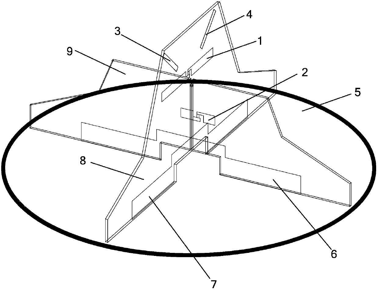
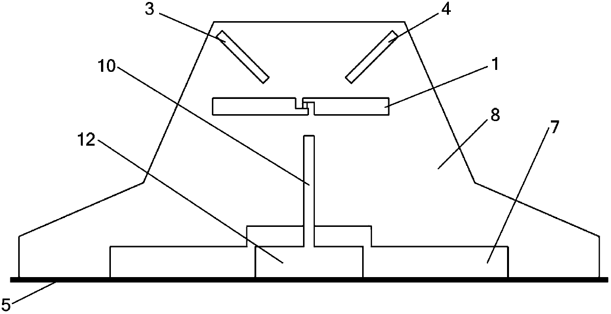
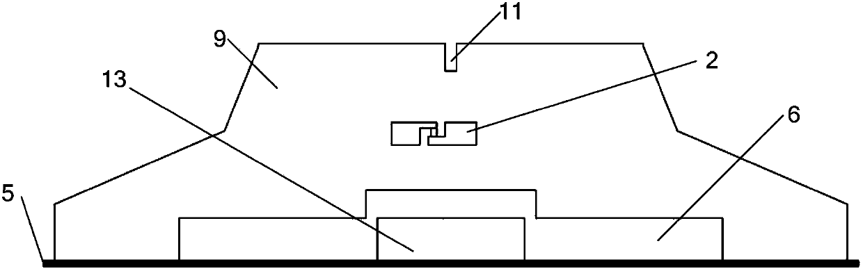
[0031] Such as figure 1 As shown, the omnidirectional antenna according to the embodiment of the present invention includes a base plate 5, and a first dielectric plate 8 and a second dielectric plate 9 arranged crosswise, the first dielectric plate 8 and the second ...


PUM


Abstract

Disclosed in the invention is an omnidirectional antenna comprising a base plate, a first dielectric plate, and a second dielectric plate. The first dielectric plate and the second dielectric plate are arranged in an intersected mode and are vertically arranged on the base plate. The first dielectric plate includes a first polaron working at a first frequency band and at least one director; and the second dielectric plate includes a second polaron working at a second frequency band. According to the invention, because the director is arranged at the dielectric plate, the antenna radiation direction can be controlled; the coverage range can be enlarged; and the quality of the received signal can be improved. Therefore, the communication quality is enhanced and the user experience is enhanced.

Description

technical field [0001] The present invention relates to the field of antennas, and in particular, to an omnidirectional antenna. Background technique [0002] Traditional ceiling antennas are designed with a metal radiator and a metal base plate, that is, using the antenna design principle of a monopole and a grounded base plate. The antenna parameters are mainly adjusted by changing the shape and size of the monopole. However, such a ceiling antenna has problems such as incomplete coverage directions and poor transmission signal quality. [0003] Similarly, the above problems also exist for antennas installed in other ways. [0004] No effective solution has been proposed yet for the problems in the related art, such as incomplete antenna coverage directions and poor signal quality, which lead to the degradation of communication quality. Contents of the invention [0005] Aiming at the problems of incomplete antenna coverage directions and poor received signal quality i...

Claims


Application Information

Patent Timeline
IPC IPC(8): H01Q1/38H01Q3/00H01Q21/30H01Q21/24H01Q1/12
Inventor 刘若鹏赵耀荣
Owner KUANG CHI INST OF ADVANCED TECH
Why Eureka
Try Eureka