Impulse type charging method and device

A charging method and pulse-type technology, applied in the field of electricity, can solve the problems of weakening, increasing the cost of chargers, high manufacturing costs, etc., and achieve the effects of low battery temperature rise and gas evolution, elimination of battery polarization, and extended battery life

Active Publication Date: 2014-05-14
无锡华汇金泽电子科技有限公司
View PDF3 Cites 2 Cited by
  • Summary
  • Abstract
  • Description
  • Claims
  • Application Information

AI Technical Summary

Problems solved by technology

[0003] The hardware chargers such as 3842 and 324 are commonly used to realize the pulse function, and the circuit is often very complicated, which will greatly increase the cost of the charger on the one hand, and on the other hand, it is often difficult to control the front and rear edges of the pulse. , the result of hard switching is that the pulse effect is often absorbed by the capacitive components in the charging circuit (such as the capacitor in the controller in the electric vehicle) and weakened
[0004] Even if the MCU is added to the low-voltage side to form a pulse with an ideal waveform through the program, compared with the current continuous pulse charging method, since the average charging current is the arithmetic mean value of the maximum value of the pulse current and the minimum value of the pulse current, the maximum value of a pulse current For 3.5A chargers, the average charging current is often only about 1.5A~2A. In order to obtain a large peak current charger power margin, it is often necessary to obtain a high manufacturing cost, which cannot adapt to the pulse charging of large-capacity batteries. need

Method used


Image

  • Impulse type charging method and device
  • Impulse type charging method and device
  • Impulse type charging method and device

Examples


Embodiment Construction

[0023] The specific implementation manners of the present invention will be further described in detail below in conjunction with the accompanying drawings and embodiments. The following examples are used to illustrate the present invention, but are not intended to limit the scope of the present invention.

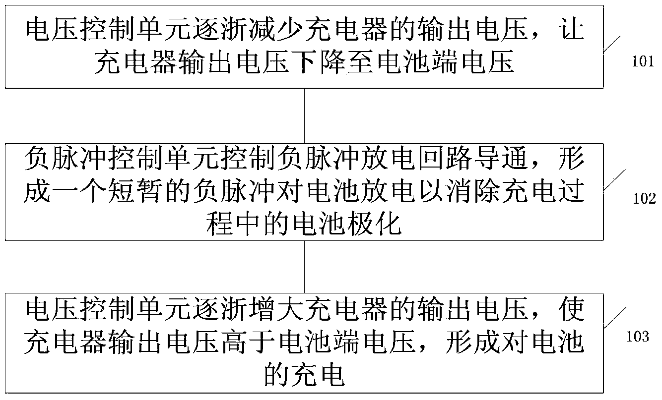
[0024] see figure 1 As shown, a pulse charging method, including:

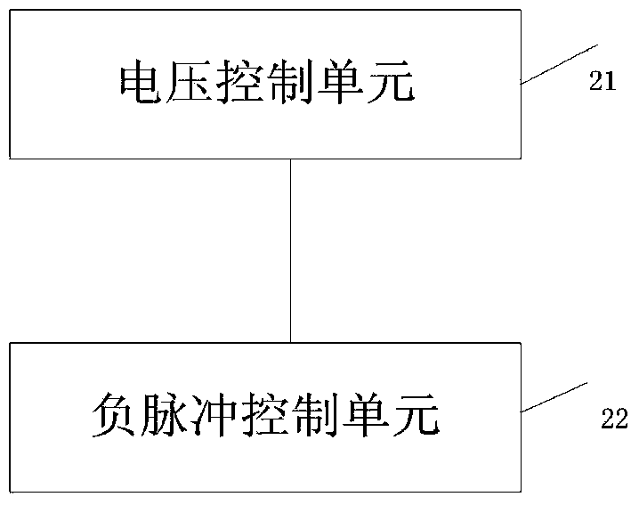
[0025] Step 101: The voltage control unit gradually reduces the output voltage of the charger, so that the output voltage of the charger drops to the terminal voltage of the battery. At this time, the electric energy stored in capacitive elements such as capacitors in other devices connected in parallel with the battery discharges the battery, making The voltage of the capacitive element also drops to the battery terminal voltage synchronously, so as to resolve the absorption of the pulse by capacitive elements such as capacitors.

[0026] Step 102: the negative pulse control unit controls the negative p...


PUM


Abstract

The invention relates to an impulse type charging method which comprises the steps that the output voltage of a charger is reduced, so that the output voltage of the charger is lowered to the voltage at the battery end; at this time, electric energy stored in a capacitive element in another device in parallel connection with a battery charges the battery, so that the voltage of the capacitive element is also lowered to the voltage at the battery end, and absorption of impulses by the capacitive element is eliminated; a negative impulse discharging loop is controlled to be switched on, so that a negative impulse is formed and used for discharging the battery, and polarization of the battery in the charging process is eliminated; the output voltage of the charger is increased, so that the output voltage of the charger is higher than the voltage at the battery end, and the battery is charged. In this way, charging efficiency is improved.

Description

technical field [0001] The invention relates to the electrical field, in particular to a pulse charging method and device. Background technique [0002] In the prior art, although pulse charging has superior performance compared to constant current charging, there are not many products in the market, and chargers that truly have the function of pulse charging are very expensive. There are two reasons for this. : [0003] The hardware chargers such as 3842 and 324 are commonly used to realize the pulse function, and the circuit is often very complicated, which will greatly increase the cost of the charger on the one hand, and on the other hand, it is often difficult to control the front and rear edges of the pulse. , the result of hard switching is that the pulse effect is often absorbed by the capacitive components in the charging circuit (such as the capacitor in the controller in the electric vehicle) and weakened. [0004] Even if the MCU is added to the low-voltage sid...

Claims


Application Information

Patent Timeline
Patent Type & Authority Applications(China)
IPC IPC(8): H02J7/00
CPCY02E60/10
Inventor 虞金中
Owner 无锡华汇金泽电子科技有限公司
Why Eureka
Try Eureka