motor

A technology of motors and engaging parts, applied in the field of motors, can solve problems such as low dimensional accuracy, difficulty in overlapping bearing parts and end plates, and inability to insert engaging parts into openings, etc., to achieve the effect of reducing size

Inactive Publication Date: 2017-01-04
SANKYO SEIKI MFG CO LTD
View PDF6 Cites 0 Cited by
  • Summary
  • Abstract
  • Description
  • Claims
  • Application Information

AI Technical Summary

Problems solved by technology

[0005] However, in the case of the structure described in Patent Document 1, since the circumferential positioning between the bearing member and the end plate is performed by fitting a plurality of engaging parts into a plurality of openings, if a plurality of engaging parts part and a plurality of openings where the dimensional accuracy is low, the engaging part cannot be fitted into the opening, and it is difficult to properly overlap the bearing part and the end plate.

Method used


Image

  • motor
  • motor
  • motor

Examples


Embodiment approach 1

[0033] the whole frame

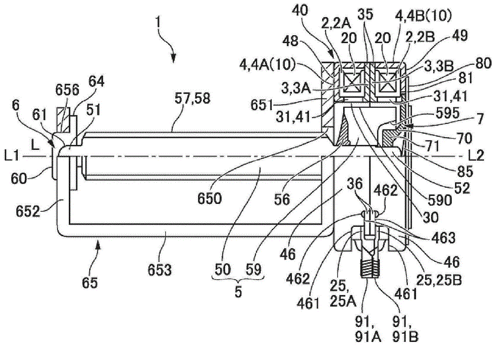
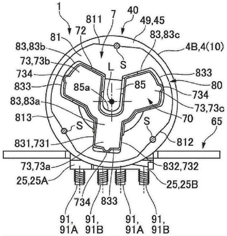
[0034] Fig. 1(a) and Fig. 1(b) are a half sectional view of the motor and a rear view of the motor seen from the side opposite to the output.

[0035]The motor 1 shown in FIG. 1( a ) and FIG. 1( b ) is a stepping motor used for driving an optical head in optical disc drive devices such as DVD and Blu-ray disc, and has a cylindrical stator 40 . The stator 40 has a structure in which an A-phase stator and a B-phase stator are arranged to overlap each other in the motor axis direction L. As shown in FIG. Therefore, in the stator 40, two annular bobbins 2 (the first bobbin 2A and the second bobbin 2B) around which the coil wire 20 is wound are overlapped in the motor axis direction L, and the bobbins 2 are respectively The inner stator core 3 and the outer stator core 4 are arranged overlappingly. More specifically, in the first bobbin 2A, an annular inner stator core 3A and an outer stator core 4A with a U-shaped cross-section are stacked on both sides ...

Embodiment approach 2

[0096] Figure 6 It is an explanatory diagram of a state where the end plate 80 is stacked on the bearing member 70 in the motor 1 according to Embodiment 2 of the present invention. In addition, in Figure 6 In , oblique lines directed downward to the right are indicated on the end plate 80 . In addition, since the basic configuration of this embodiment is the same as that of Embodiment 1, the same reference numerals are attached to the common parts and their descriptions are omitted.

[0097] In Embodiment 1, the convex portion 734 for radial positioning between the bearing member 70 and the end plate 80 is formed on the engaging portion 73 of the bearing member 70, but in this embodiment, as Figure 6 A convex portion 834 protruding toward the engaging portion 73 is formed at the end portion 833 of the opening portion 83 of the end plate 80 as shown, and the convex portion 834 has a semicircular planar shape.

[0098] Also in this configuration, as in Embodiment 1, the end ...

Embodiment approach 3

[0100] Figure 7 It is a sectional view of the end plate 80 of the motor 1 according to Embodiment 3 of the present invention. In addition, since the basic structure of this embodiment is the same as that of Embodiment 1, the same code|symbol is attached|subjected to a common part, and the description is abbreviate|omitted.

[0101] In Embodiment 1, the edge of the outer peripheral surface of the engaging portion 73 opposite to the side where the stator 40 is located forms the tapered surface 76. However, in the present embodiment, as Figure 7 In the inner peripheral surface of the opening 83 of the end plate 80 shown, the edge on the side where the stator 40 is located (the output side L1 ) forms a tapered surface 86 .

[0102] According to such a structure, since the engaging part 73 can be easily fitted into the opening part 83, the bearing member 70 and the end plate 80 can be superimposed efficiently.

[0103] In addition, when the convex portion 834 is provided on the...


PUM


Abstract

A motor enables a bearing part and an end plate to overlap in a highly efficiency manner to keep a proper position relationship between the bearing part and the end plate. In the motor (1), when the structure of a bearing part (70) configured on an end portion of a stator (40) and maintained between an end plate (80) and the stator (40) via the end plate (80) is arranged, multiple positions of the bearing part (70) at the periphery are provided with clamping portions (73) that overlap an end surface (49) of the stator (40), and multiple positions of the end plate (80) at the periphery are equipped with opening portions (83) for insertion of the multiple clamping portions (73). When side portions (731, 732) of the clamping portions (73) of the bearing part (70) contact with side portions (831, 832) of the opening portions (83) of the end plate (80) for circumferential positioning between the bearing part (70) and the end plate (80), positioning is achieved through one clamping portion (73a) and one opening portion (83a) of the multiple positions.

Description

technical field [0001] The invention relates to a motor in which bearing components are held at the ends of a stator by means of end plates. Background technique [0002] For motors such as stepping motors, when constituting a bearing mechanism for rotatably supporting a rotating shaft, a structure in which a bearing member disposed at an end portion of a stator is held between an end plate and a stator via an end plate (refer to Patent Document 1). [0003] In the motor with the above structure, the bearing member has rectangular engaging portions overlapping with the end surface of the stator at a plurality of positions in the circumferential direction, and the end plate has a plurality of engaging portions respectively fitted in at a plurality of positions in the circumferential direction. Rectangular shaped opening. Therefore, since the end plate does not overlap with the engaging portion of the bearing member in the motor axis direction, the size in the motor axis dir...

Claims


Application Information

Patent Timeline
Patent Type & Authority Patents(China)
IPC IPC(8): H02K5/16
Inventor 米山秀和
Owner SANKYO SEIKI MFG CO LTD
Why Eureka
Try Eureka