
AC motor revolving speed tracking method, speed control device and AC motor

A technology of AC motors and speed regulating devices, which is applied in the direction of controlling electromechanical transmission devices, controlling generators, motor generators, etc. It can solve problems such as large speed gap, overcurrent, and difficulty in determining the first control signal, etc., and achieves estimation The effect of wide speed range, short speed search time and controllable speed search time

Active Publication Date: 2014-05-14
CHANGSHU SWITCHGEAR MFG CO LTD (FORMER CHANGSHU SWITCHGEAR PLANT)
View PDF7 Cites 8 Cited by
  • Summary
  • Abstract
  • Description
  • Claims
  • Application Information

AI Technical Summary

Problems solved by technology

[0005] The technical solutions recorded in the above documents have the following problems: 1) It is not easy to determine the first control signal. If the setting is not appropriate, it is likely to cause overcurrent or overvoltage faults.
2) If there is a large gap between the current searched stator magnetic field frequency and the actual speed of the induction motor, especially when the stator magnetic field frequency is in the opposite direction to the actual speed of the induction motor, then the search time of the speed search device will be longer
Therefore, this scheme has certain limitations in practical application.

Method used


Image

  • AC motor revolving speed tracking method, speed control device and AC motor
  • AC motor revolving speed tracking method, speed control device and AC motor
  • AC motor revolving speed tracking method, speed control device and AC motor

Examples


Embodiment Construction

[0038] The technical scheme of the present invention is described in detail below in conjunction with accompanying drawing:

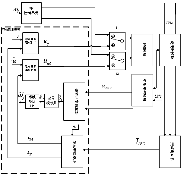
[0039] figure 1A structural block diagram of an embodiment of the AC motor of the present invention is shown, as shown in the figure, the AC motor of the present invention includes an AC motor and a speed regulating device, and the speed regulating device includes: a PWM module, an inverter module and a voltage reconstruction module, The PWM module modulates the input voltage signal into the input control signal of the inverter module. The inverter module drives the AC motor according to the control signal output by the PWM module. The voltage reconstruction module collects the bus voltage Udc and the control signal output by the PWM module. Calculate the stator voltage vector As shown in the figure, the speed control device of the present invention also includes a speed search module (shown in the dotted box in the figure), and the speed search modul...


PUM


Abstract

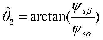
The invention discloses an AC motor revolving speed tracking method which is used to track a revolving speed when an AC motor restarts. The method includes the following steps: 1, a current flux linkage angle is estimated; 2, a stator current vector carries out coordinate conversion so as to obtain a first current value and a second current value which are respectively in line with and perpendicular to the flux linkage angle; 3, the first current value and a preset non-zero current values serve as input, and through calculation of a current regulator, a voltage is obtained (img file = 'dest_path_image002. TIF' wi = '24' he = '16' / ); the second current value and 0 serve as input, and through calculation of the current regulator, a voltage is obtained (img file = 'dest_path_image004. TIF' wi = '16' he = '16' / ); 4, voltages (img file ='891979dest_path_image002. TIF' wi = '24' he = '16' / ) and (img file ='996071dest_path_image004. TIF' wi ' = '16' he = '16' / ) carry out pulse width modulation to generate a driving control signal to drive the AC motor; and 5, steps from 1 to 4 are repeated, until the second current value is lower than a current threshold value and maintains for a period of a preset time, and differential calculation of a current flux angle is carried out to get the revolving speed when the AC motor restarts. The invention also discloses an AC motor speed control device and the AC motor. According to the invention, the advantages of being fast, accurate and low-cost are realized.

Description

technical field [0001] The invention relates to a speed tracking method of an AC motor, a speed regulating device and the AC motor, and belongs to the technical field of AC motors. Background technique [0002] Due to the complexity of the industrial application site and the variety of process requirements, it is determined that the frequency conversion speed regulation system must have sufficient processing capacity for abnormal operating conditions in addition to the performance requirements during normal operation. For example, large ventilation equipment may cause the motor to reverse freely due to the residual air volume in the air duct. After a large inertia load encounters a sudden power failure, the motor will rotate freely for a long time, up to tens of minutes; The motor may be in a state of large slip and fail to start (over-current protection). In order to prevent this phenomenon, after the power supply returns to normal, the speed control system of the motor is...

Claims


Application Information

Patent Timeline
Patent Type & Authority Applications(China)
IPC IPC(8): H02P21/14H02P21/00
Inventor 唐雪峰顾鸣刚刘奕骋李志鹏管瑞良
Owner CHANGSHU SWITCHGEAR MFG CO LTD (FORMER CHANGSHU SWITCHGEAR PLANT)
Learn More