Drill Body for Indexable Drills

A drill and main body technology, applied in the field of indexable drills, can solve the problems of reduced durability, increased cutting resistance, restricted processing conditions, etc., and achieves the effects of high rigidity, high chip discharge performance, and improved chip discharge performance.

Active Publication Date: 2017-07-21
OSG
View PDF1 Cites 1 Cited by
  • Summary
  • Abstract
  • Description
  • Claims
  • Application Information

AI Technical Summary

Problems solved by technology

[0007] However, in such conventional indexable drills, it is not always possible to obtain sufficient chip discharge performance, and there are problems in that durability (tool life) decreases due to chip clogging, wear, chipping, fracture, etc., or Drilling becomes unstable or processing conditions are restricted due to increased cutting resistance due to chip clogging

Method used


Image

  • Drill Body for Indexable Drills
  • Drill Body for Indexable Drills
  • Drill Body for Indexable Drills

Examples


Embodiment

[0035] Hereinafter, embodiments of the present invention will be described in detail with reference to the drawings.

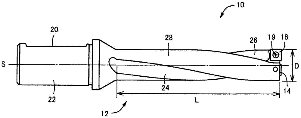
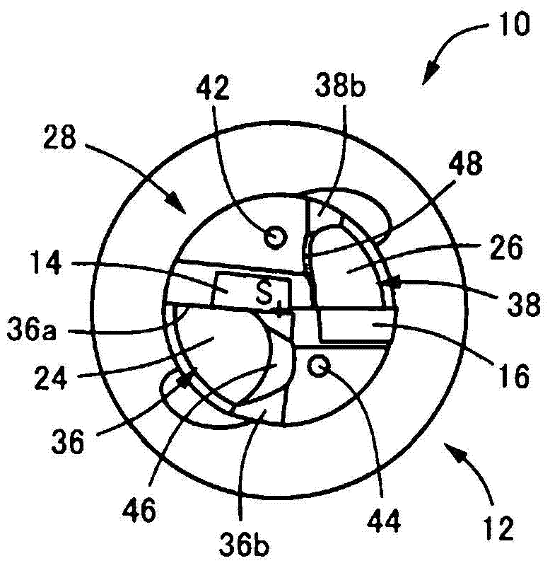
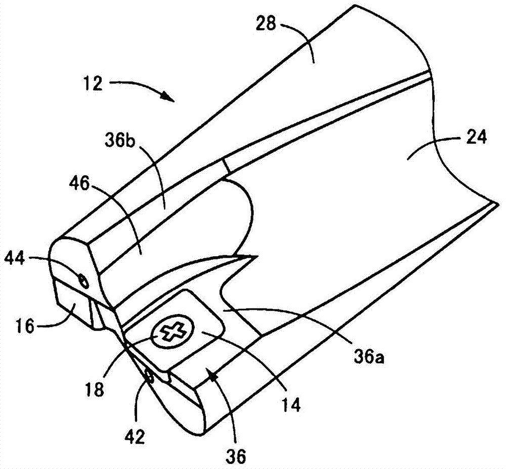
[0036] figure 1 It is a top view of an indexable drill 10 according to an embodiment of the present invention viewed from a direction perpendicular to the axis S, figure 2 is from the front side ( figure 1 The right side of ) observes and magnifies the magnified bottom view shown, image 3 It is a perspective view enlargedly showing a front end part. The indexable drill 10 is used by integrally detachably attaching a pair of inner inserts 14 and outer inserts 16 to the front end portion of a cylindrical drill body 12 via attachment screws 18 , 19 . The inner insert 14 cuts the center of the hole and is attached near the axis S of the drill body 12 , and the outer insert 16 cuts the outer periphery of the hole and is attached to the outer periphery of the drill body 12 . These inner blades 14 and outer blades 16 are formed into a square flat plate shape by...


PUM

PropertyMeasurementUnit
surface roughnessaaaaaaaaaa
mean roughnessaaaaaaaaaa

Abstract

A pair of first helical grooves (24) and second helical grooves (26) provided on the drill body (12) of the indexable drill bit (10) are hardened and heat-treated by a ball end mill Since the cutting process performed at (30, 32) is mirror-finished, friction on the inner surface of the groove is reduced, and chips are well discharged. Accordingly, even in the indexable drill (10) for deep hole machining having a long flute length (L), wear, chipping, fracture, etc. due to chip clogging can be suppressed, and durability (tool life) is improved. In addition, the increase in cutting resistance due to chip clogging can be suppressed, stable drilling can be performed, and the limit machining conditions that can be drilled are relaxed, and the machinable area can be expanded.

Description

technical field [0001] The present invention relates to an indexable drill, and particularly relates to a drill body capable of obtaining excellent chip discharge performance even in a drill for deep hole machining whose flute length L is 4D or more relative to the drill diameter D. Background technique [0002] There is known an indexable drill in which a pair of first helical grooves and a second helical groove are provided on the outer peripheral surface of a cylindrical drill body, and a pair of holes are attached to the front end of the first helical grooves. The inner edge insert for cutting on the center side, and the outer edge insert for cutting the outer peripheral side of the hole is installed on the front end of the second helical groove. The first helical groove and the second helical groove discharge chips to the shank side (refer to Patent Document 1). [0003] prior art literature [0004] patent documents [0005] Patent Document 1: Japanese Patent Applic...

Claims


Application Information

Patent Timeline
Patent Type & Authority Patents(China)
IPC IPC(8): B23B51/00B23P15/32
CPCB23B51/0493B23P15/32B23B2251/408B23B51/063Y10T408/9097B23B2251/14B23B2251/402B23B2251/404B23B51/00
Inventor 青山拓磨
Owner OSG
Why Eureka
Try Eureka