A charging pole for EV and a detecting method thereof

A charging pile and charging coupler technology, applied in electric vehicle charging technology, electric vehicles, charging stations, etc., can solve problems such as the danger of charging piles

Active Publication Date: 2014-05-14
北京ABB低压电器有限公司
View PDF4 Cites 13 Cited by
  • Summary
  • Abstract
  • Description
  • Claims
  • Application Information

AI Technical Summary

Problems solved by technology

Electrical parts are exposed and accessible, which makes the charging

Method used


Image

  • A charging pole for EV and a detecting method thereof
  • A charging pole for EV and a detecting method thereof
  • A charging pole for EV and a detecting method thereof

Examples


Embodiment Construction

[0034] The subject matter of the invention will be explained in more detail with reference to the accompanying drawings, in which a preferred typical embodiment is shown.

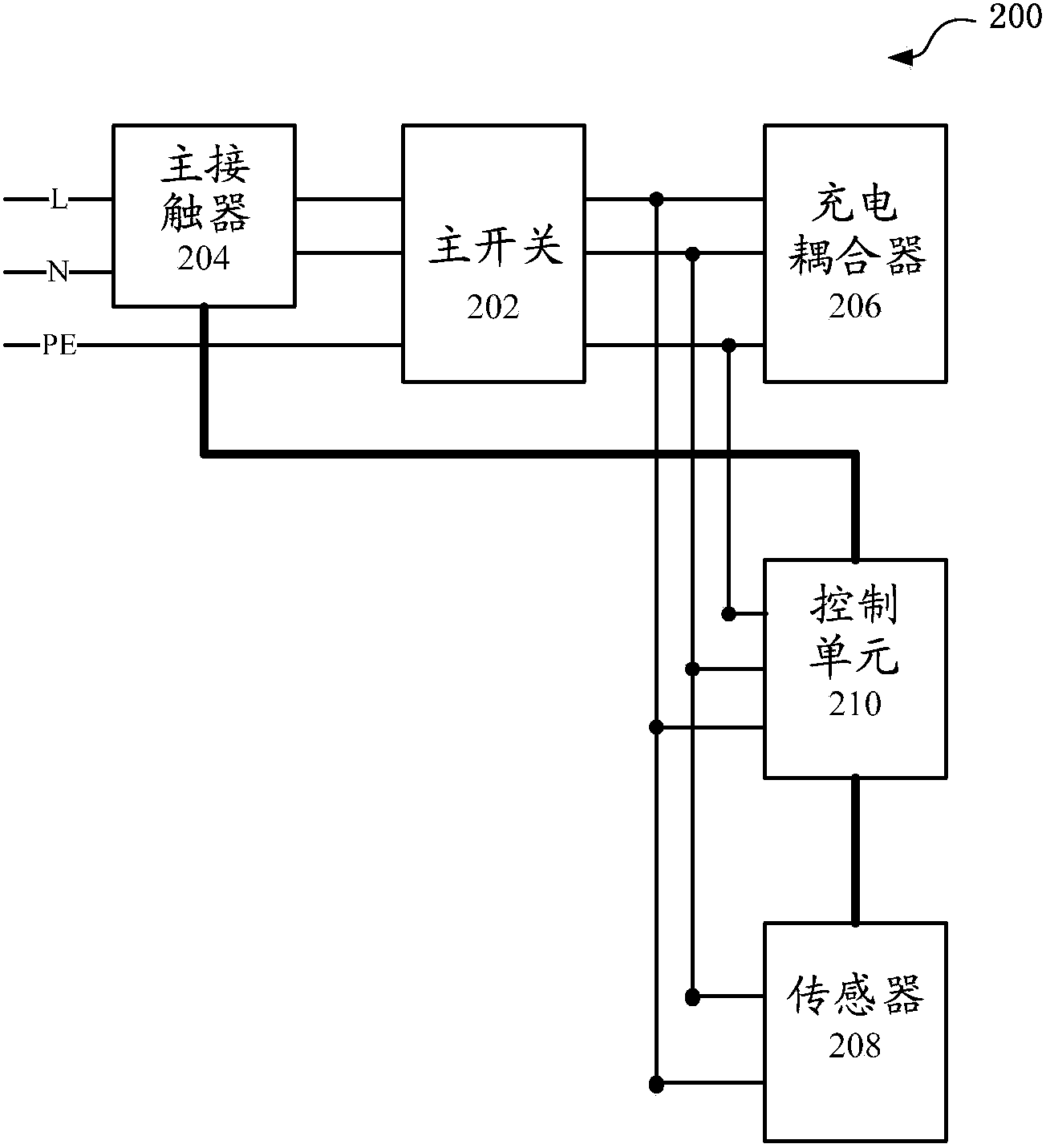
[0035] figure 2 The structure of the charging pile according to the embodiment of the present invention is shown.

[0036] In order to protect customers from danger (such as electric shock), the charging pile includes at least one sensor, which is used to detect the acceleration of the charging pile due to an instantaneous external force (such as a collision caused by an electric vehicle driver's misoperation); when the acceleration When the preset critical value is exceeded, the charging pile will be powered off. In particular, the sensor is an acceleration sensor made of a semiconductor.

[0037] Such as figure 2 As shown, the charging pile 200 includes a main switch 202, a main contactor 204, a charging coupler 206, a sensor 208 and a control unit 210; wherein, the main switch 202, the main contacto...


PUM


Abstract

A charging pole for electric vehicle (EV) and a detecting method thereof. The charging pole (300) comprises a main switch (302), a main contactor (304), a second contactor (305), a charging coupler (306), at least one sensor (308) and a control unit (310). The sensor is used to detect acceleration and/or a tilt angle of the charging pole due to a transient outside force, for example a collision force caused by the EV driver's mis-operation. When the acceleration and/or the tilt angle is beyond a preset threshold, the control unit will instruct the main contactor to break the power contact of the charging coupler, so that the charging pole will be power-off.

Description

technical field [0001] The present invention relates to a charging technology for an electric vehicle (EV), and more particularly, to a charging pile for an electric vehicle and a detection method thereof. Background technique [0002] Clean energy, especially electric vehicles, is attracting more and more attention due to skyrocketing gasoline prices. Charging stations, similar to gas stations for cars, provide electricity for electric vehicles. Generally speaking, there are two charging solutions for electric vehicles, one is to build charging piles and supply alternating current (AC) or direct current (DC); the other is to build battery replacement stations to supply rechargeable batteries to replace almost Drained battery. [0003] Currently, AC charging mode takes longer to complete charging than DC mode. For example, the AC mode takes 5-8 hours, and customers can self-charge on the charging piles at home, in the office parking lot, or in some public facility parking...

Claims


Application Information

Patent Timeline
IPC IPC(8): H02J7/00H02H5/00
CPCB60L3/0007B60L3/04B60L53/30B60L53/31Y02T10/70Y02T10/7072Y02T90/12
Inventor 刘坤伦D·马拉卡尔扎樊震
Owner 北京ABB低压电器有限公司
Why Eureka
Try Eureka