Special machine tool and processing method for plane processing of large equipment

A technology of plane processing and processing methods, which is applied in the direction of metal processing machinery parts, milling machine equipment, milling machine equipment details, etc., can solve the problems of difficult guarantee of processing accuracy, extended bridge crane manufacturing period, height less than 3 meters, etc., to avoid Manpower grinding, saving labor and saving time

Active Publication Date: 2016-03-09
QINGDAO PORT INT
View PDF4 Cites 0 Cited by
  • Summary
  • Abstract
  • Description
  • Claims
  • Application Information

AI Technical Summary

Problems solved by technology

However, when the size of the beam is too large, it makes the processing very difficult. For example, in a large bridge crane, the size of the beam reaches 3 meters high and 30 meters long, which makes it difficult to process the four joint surfaces on the beam. One is the milling of the existing milling machine. The height of the head is less than 3 meters, and the second is that the size of the beam is too large to enter the workshop; the current solution is to process the joint surface of the beam by manual grinding. Since the area of ​​each joint surface is also large, the length 2.6 meters wide and 1.6 meters wide, this prolongs the manufacturing period of the bridge crane and requires a lot of manpower and labor intensity. Since many people work at the same time, the machining accuracy is not easy to guarantee

Method used


Image

  • Special machine tool and processing method for plane processing of large equipment
  • Special machine tool and processing method for plane processing of large equipment
  • Special machine tool and processing method for plane processing of large equipment

Examples


Embodiment Construction

[0044] In order to make the purpose, technical solutions and advantages of the embodiments of the present invention more clear, the technical solutions in the embodiments of the present invention will be clearly and completely described below in conjunction with the drawings in the embodiments of the present invention.

[0045] In the description of the present invention, it should be noted that the orientation or positional relationship indicated by the terms "upper", "lower", "left", "right", etc. is based on the positional relationship shown in the drawings, and is only for the convenience of description The present invention and simplified description do not indicate or imply that the device or element referred to must have a specific orientation, be constructed and operate in a specific orientation, and thus should not be construed as limiting the present invention.

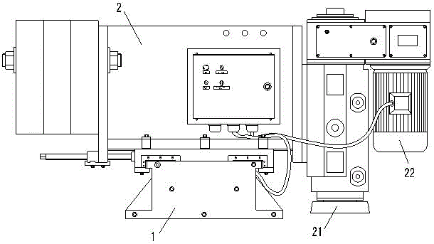
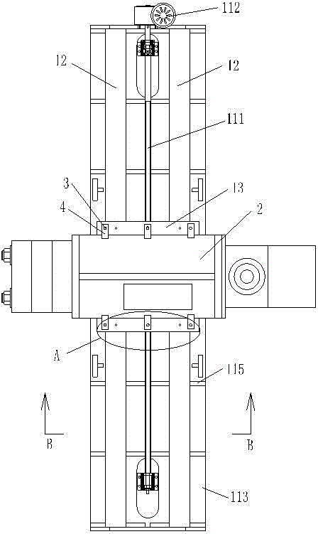
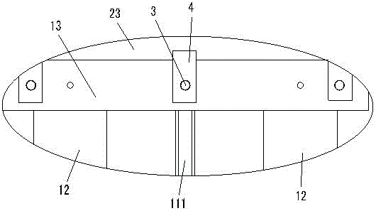
[0046] refer to Figure 1-7, is an embodiment of the special-purpose machine tool for large-scale equipme...


PUM


Abstract

The invention provides a special machine tool for machining the plane of large equipment and a machining method. The special machine tool comprises a machine body and a power milling head, wherein the machine body comprises a base, guide rails and a sliding block; the guide rails are fixed on the base; the sliding block is positioned on the guide rails; the power milling head is arranged on the sliding block; the two guide rails parallel to each other are fixed on the base; two grooves matched with the two guide rails are formed in the lower end of the sliding block; the guide rails penetrate through the grooves; a screw rod parallel to the guide rails is arranged on the base; a nut matched with the screw rod is fixed at the lower end of the sliding block; the screw rod penetrates through the nut; a screw rod motor which drives the screw rod to rotate is also arranged on the base; the power milling head has a left fixing position and a right fixing position, capable of being exchanged, on the sliding block. Due to the arrangement of the special machine tool for machining the plane of the large equipment, the plane of the large equipment is prevented from being manually ground, a great amount of labor is saved, the labor intensity is reduced, and the plane machining speed of the large equipment is increased, and the machining accuracy is improved.

Description

technical field [0001] The invention belongs to the technical field of milling processing equipment, and in particular relates to a special machine tool for plane processing of large-scale equipment, and a processing method of using the special machine tool to process the flange surface of a bridge suspension beam. Background technique [0002] In port operations, it is necessary to use bridge cranes to lift containers for loading and unloading operations. With the development of the container transportation industry, bridge cranes are also continuously upgraded to increase lifting capacity, lifting height, forward distance, and increase loading and unloading speed. At the same time, the volume of the bridge crane increases, so the volume of the structural parts that make up the bridge crane also increases; at the same time, the requirements for the joint surface between some structural parts are relatively high, so the processing accuracy of the joint surface on the structur...

Claims


Application Information

Patent Timeline
Patent Type & Authority Patents(China)
IPC IPC(8): B23C3/00B23Q5/40
Inventor 李建文李永刚周俊克
Owner QINGDAO PORT INT
Why Eureka
Try Eureka