covered container

A container and container body technology, which is applied in the directions of cover, clothing, exhaust device, etc., can solve the problems of reduced thermal insulation performance, inserting thermal insulation materials, etc., and achieves the effects of high thermal insulation performance, easy decomposition and assembly

Active Publication Date: 2017-08-25
THERMOS LLC +1
View PDF7 Cites 0 Cited by
  • Summary
  • Abstract
  • Description
  • Claims
  • Application Information

AI Technical Summary

Problems solved by technology

Therefore, it is impossible to insert a heat insulating material in the outer cover, and there is a problem that the thermal insulation performance is lowered.

Method used


Image

  • covered container
  • covered container
  • covered container

Examples


Embodiment 1

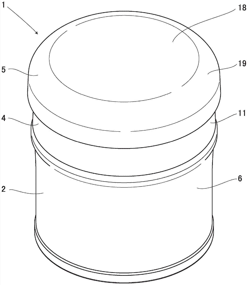
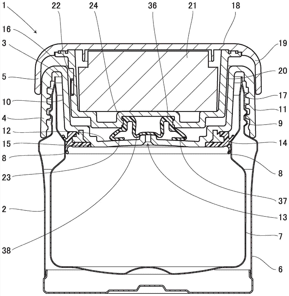
[0037] Below, according to Figure 1 to Figure 7 Example 1 will be described. figure 1 Shown is a covered container 1 of the present invention. The covered container 1 is composed of: a container body 2 having a heat-insulating double-layer structure; a lower cover 4 for covering an upper opening 3 of the container body 2 ; and an upper cover 5 attached to the lower cover 4 .

[0038] The container body 2 is composed of a bottomed cylindrical outer tube 6 and an inner tube 7 accommodated inside the outer tube 6 . By joining the upper ends of the outer cylinder 6 and the inner cylinder 7 , it is possible to form a heat-insulating double-layer container having a vacuum layer as a heat-insulating layer between the outer cylinder 6 and the inner cylinder 7 . Further, the inner cylinder 7 of the container body 2 is provided with a waterproof portion 8 protruding inward on the upper inner peripheral surface. In addition, a male thread 9 is provided on the upper peripheral surface...

Embodiment 2

[0056] Next, other examples will be described. Wherein, the parts that are the same as those in Embodiment 1 are denoted by the same symbols, and the detailed description of these parts will be omitted.

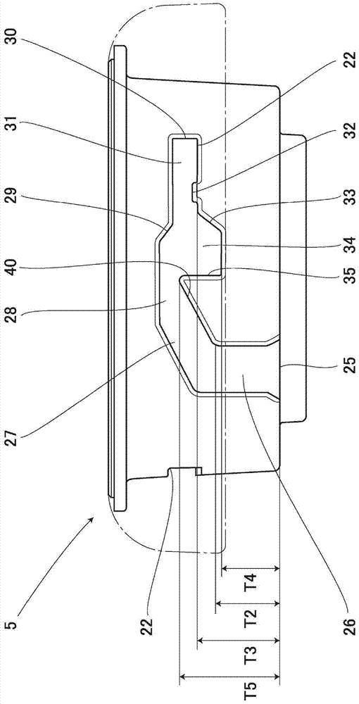
[0057] Figure 8 Example 2 is shown. Although in Embodiment 1, the upper part of the inner peripheral surface of the lower cover 4 is provided with engaging protrusions 16, and the engaging protrusions 16 are provided at three positions of the inner peripheral surface at equal distances from each other, but in In the second embodiment, the engaging protrusion 16 is replaced by an engaging groove 22 . In addition, although in Embodiment 1, the outer peripheral surface of the second trunk portion 20 of the upper cover 5 is provided with an engaging groove 22, and the engaging groove 22 is provided on the outer peripheral surface in a state corresponding to the engaging protrusion 16. However, in Example 2, the engaging groove 22 is replaced by an engaging protrusion 16 . In...


PUM


Abstract

PROBLEM TO BE SOLVED: To provide a container with a lid of which an upper lid and a lower lid can be removed integrally, and which can be securely and easily released even when an inside of a container main body is in a depressurized state, is hygienic, and exhibits high heat-insulation capacity.SOLUTION: A container includes a container main body 2 having an opening part, a lower lid 4 screwed with the container main body 2, and an upper lid 5 fitted to the lower lid 4. The lower lid 4 includes an air hole 13 arranged in a center part and communicating between an inside and an outside, and an elastic packing 14 arranged in a lower part and abutting on an inner surface of the container main body 2. The upper lid 5 includes an air hole closing packing 23 having an elastic closing part 38 in a position opposite to the air hole 13. An engagement protrusion 16 as a protruded engagement part is arranged one of an inner wall of the lower lid 4 or an outer wall of the upper wall 5. On the other of them, an engagement groove 22 which houses the engagement protrusion 16 and has an open state storage part 34 for holding an open state of the upper lid 5 and a close state storage part 31 for holding a close state is arranged. Thereby, the container can be opened while maintaining the integrated state of the upper lid 5 and the lower lid 4.

Description

technical field [0001] The present invention relates to a container with a lid. Background technique [0002] Conventionally, a container disclosed by, for example, Patent Document 1 is known as the above-mentioned type of covered container. The container has: a heat-retaining container main body formed with an upper opening; an inner cover that is detachably provided to close the upper opening of the heat-retaining container main body; and an outer cover that covers the upper part of the inner cover. Screw and install on the outer peripheral surface of the heat preservation container. Wherein, the inner cover is provided with an air passage connecting the inside and the outside, and the air passage is sealed by the air hole blocking packing of the upper cover. By adopting such a structure, even when the inside of the thermal insulation container is in a depressurized state, outside air can be introduced through the air hole, and the inside of the container can be returned...

Claims


Application Information

Patent Timeline
Patent Type & Authority Patents(China)
IPC IPC(8): B65D51/18A45C11/20
CPCB65D41/0407B65D51/1633B65D81/3837B65D2205/00
Inventor 渡边麻子
Owner THERMOS LLC
Why Eureka
Try Eureka