Lifting device

A lifting device and mounting frame technology, applied in storage devices, transportation and packaging, etc., can solve the problems of shortening the service life of the equipment, difficult to guarantee the movement stability, easy jamming and failure of the load, etc., so as to reduce the transmission error and improve the The effect of accuracy and load capacity

Active Publication Date: 2014-05-21
SIASUN CO LTD
View PDF17 Cites 15 Cited by
  • Summary
  • Abstract
  • Description
  • Claims
  • Application Information

AI Technical Summary

Problems solved by technology

[0002] The lifting device of the existing stacker inside the stocker is two synchronous belts, and each synchronous belt has a driving wheel and an idler wheel at both ends, which are driven by the same driving motor with two-way output, and the output shaft drives the wheels at both ends. The two synchronous belt pulleys rotate, and then drive the idler gear through the synchronous belt pulley transmission to realize the circular movement of the synchronous belt. The load is fixed at a fixed position on one side of the synchronous belt. For stability, the two ends of the load limit the degree of freedom through the rollers. The disadvantages of synchronous belt transmission are: the installation load must be installed eccentrically, the greater the rise height, the greater the torque on the supporting beam column, reducing the service life of the equipment, because the loads at both ends of the synchronous belt are not completely symmetrical, the movement of the load is stable It is difficult to guarantee the reliability, large transmission errors will occur, and the efficiency is low. Moreover, the existing way of fixing the guide rail sliders on both sides of the equipment makes the installed load prone to jamming and failure, and damages the equipment. The installation method of the rollers on both sides low movement precision

Method used


Image

  • Lifting device
  • Lifting device
  • Lifting device

Examples


Embodiment Construction

[0010] Embodiments of the present invention are described in detail below, examples of which are shown in the drawings, wherein the same or similar reference numerals designate the same or similar elements or elements having the same or similar functions throughout. The embodiments described below by referring to the figures are exemplary only for explaining the present invention and should not be construed as limiting the present invention.

[0011] In the description of the present invention, the orientation or positional relationship indicated by the terms "inner", "outer", "longitudinal", "transverse", "upper", "lower", "top", "bottom" etc. are based on the drawings The orientations or positional relationships shown are only for the convenience of describing the invention and do not require the invention to be constructed and operated in a specific orientation, and thus should not be construed as limitations on the invention.

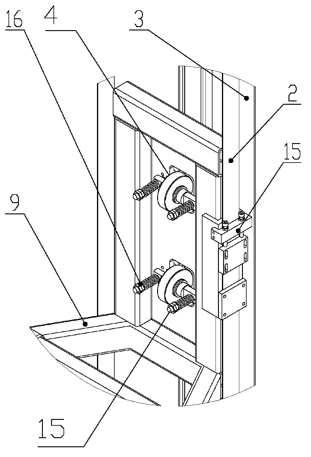
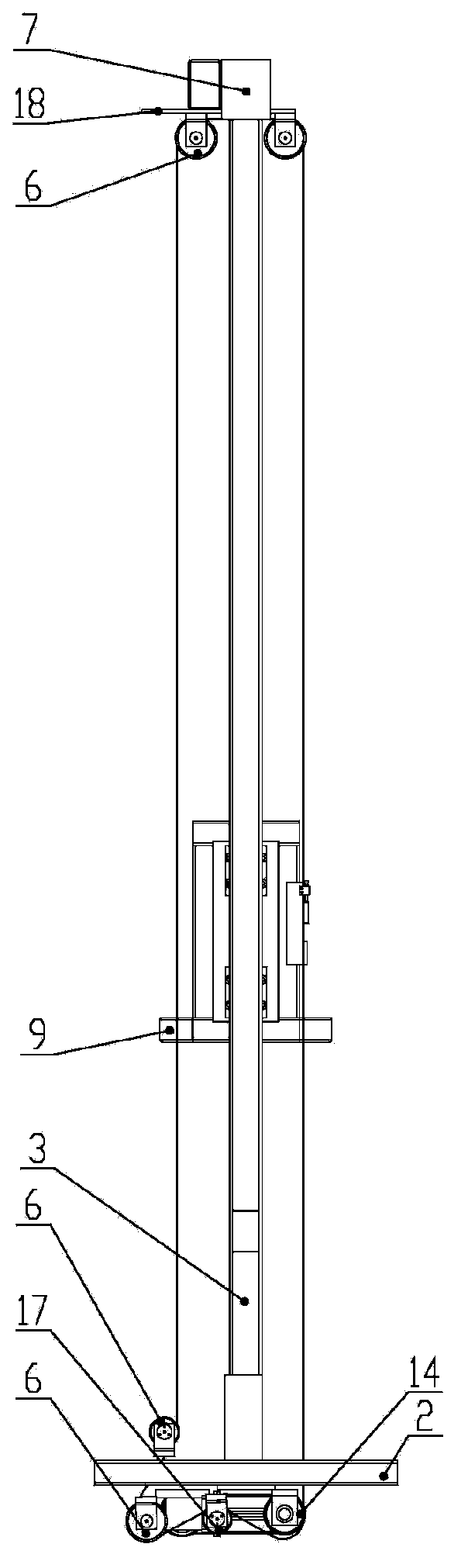
[0012] see figure 1 , which is a perspective...


PUM


Abstract

A lifting device comprises a bottom installation frame, a first side supporting column, a second side supporting column, a top supporting frame, idler wheels, an idler wheel rail, a fixed guide rail, sliding blocks, a regulating device, a load containing platform, a top idle pulley installation board and a plurality of idle pulleys, wherein the idle pulleys are arranged on the upper side and the lower side of the bottom installation frame and the lower edge of the top idle pulley installation board; the top supporting frame, the first side supporting column, the second side supporting column and the bottom installation frame are vertically arranged; the top idle pulley installation board is arranged on the lower edge of the top supporting frame; the fixed guide rail and the idler wheel rail are arranged on the first side supporting column and the second side supporting column respectively; one side of each sliding block is connected with the fixed guide rail, and the other side of each sliding block is fixed on the load containing platform; the idler wheels make contact with the idler wheel rail and are fixed on the load containing platform through the regulating device. The lifting device effectively reduces the number of transmission errors, and improves lifting accuracy and load capability.

Description

technical field [0001] The invention relates to an automatic conveying device, in particular to a lifting device for a manipulator inside a stacker in a stocker. Background technique [0002] The lifting device of the existing stacker inside the stocker is two synchronous belts, and each synchronous belt has a driving wheel and an idler wheel at both ends, which are driven by the same driving motor with two-way output, and the output shaft drives the wheels at both ends. The two synchronous belt pulleys rotate, and then drive the idler gear through the synchronous belt pulley transmission to realize the circular movement of the synchronous belt. The load is fixed at a fixed position on one side of the synchronous belt. For stability, the two ends of the load limit the degree of freedom through the rollers. The disadvantages of synchronous belt transmission are: the installation load must be installed eccentrically, the greater the rise height, the greater the torque on the s...

Claims


Application Information

Patent Timeline
Patent Type & Authority Applications(China)
IPC IPC(8): B65G1/04
Inventor 李学威温燕修曲征辉管莉娜何以刚边弘晔
Owner SIASUN CO LTD
Why Eureka
Try Eureka