Open-end spinning rotor

A free-end and rotor technology, which is applied in the direction of free-end spinning machines, spinning machines, continuous winding spinning machines, etc., can solve the problem of unreliable torque transmission

Active Publication Date: 2014-05-21
SAURER GERMANY GMBH & CO KG
View PDF8 Cites 1 Cited by
  • Summary
  • Abstract
  • Description
  • Claims
  • Application Information

AI Technical Summary

Problems solved by technology

However, it has also been shown that this type of non-positive torque transmission does not have the required reliability
The document does not make any statement about unbalanced forces

Method used


Image

  • Open-end spinning rotor
  • Open-end spinning rotor
  • Open-end spinning rotor

Examples


Embodiment Construction

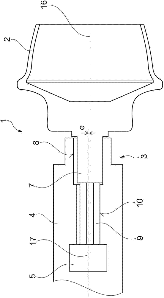
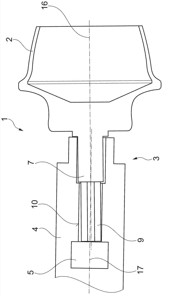
[0028] figure 1 and figure 2 A spinning rotor 1 is shown with a connecting device 3 as known in the prior art, for example from the previously cited document EP1156142B1. The problem improved by the invention will be explained with the aid of these two diagrams. figure 1 and figure 2 Both show the same spinning rotor 1, so the spinning rotor 1 will only be described once in the following. The spinning rotor 1 comprises a rotor cup 2 and a rotor shaft 4 interconnected by a connecting device 3 . The rotor shaft 4 is mounted to a suitable device (not shown) and connected to a drive (not shown). The drive rotates the rotor shaft 4 and thus the spinning rotor 1 . The rotor cup 2 has appendages. This appendage is subdivided into a cylindrical guide appendage 7 and a form-fitting locking element 9 . In the present illustration, the form-fitting locking element 9 is configured as an outer polygon. The rotor shaft 4 has a cylindrical bore portion 8 corresponding to the cylind...


PUM


Abstract

The invention relates to an open-end spinning rotor (1 a, 1 b, 1 c) comprising a rotor shaft (4a, 4b, 4c), a rotor cup (2, 2c) and a coupling device (3a, 3b, 3c). The rotor shaft (4a, 4b, 4c) and the rotor cup (2, 2c) are releasbly connected together by means of the coupling device (3a, 3b, 3c). The coupling device (3a, 3b, 3c) is provided with a locking means (5, 6) for the axial arresting of the rotor cup (2, 2c), a transmission means (9, 10, 11, 12) for positively transmitting a torque from the rotor shaft (4a, 4b, 4c) to the rotor cup (2, 2c), and a centering means used for aligning the rotor shaft (4a, 4b, 4c) with the rotor cup (2, 2c). The centering means comprises a cylindrical bore part (8, 8C) and a corresponding guide extension part (7, 7c) to be guided into the cylindrical bore part (8, 8C). According to the invention, the cylindrical bore part (8, 8C) and the guide extension part (7, 7c) are in clearance fit with each other. The centerin means comprises elastic arrangements (13, 14, 15B, 15c) arranged between the cylindrical bore part (8, 8C) and the guide extension part (7, 7c).

Description

technical field [0001] The present invention relates to an open-end spinning rotor, which comprises: a rotor shaft, a rotor cup and a connecting device, the connecting device connects the rotor shaft and the rotor cup in a releasable manner . The connecting device has a locking device for axially locking the rotor cup, a transmission device for transmitting torque from the rotor shaft to the rotor cup in a form-fitting manner, and additionally for connecting the rotor shaft to the rotor cup. A centering device for centering the rotor cup. The centering device comprises a cylindrical bore and a guide appendage corresponding to the cylindrical bore and capable of being introduced into the cylindrical bore. Background technique [0002] A spinning rotor that has been inserted into an open-end rotor spinning machine must be able to be replaced if necessary, for example in the event of wear or in order to produce a different type of yarn on the rotor spinning machine. Dependin...

Claims


Application Information

Patent Timeline
Patent Type & Authority Applications(China)
IPC IPC(8): D01H4/10D01H4/12
CPCD01H4/10
Inventor H-G·瓦森霍芬
Owner SAURER GERMANY GMBH & CO KG
Why Eureka
Try Eureka