Method for embedment of grouting hole in base plate of underground chamber

A technology for underground caverns and grouting holes, which is applied in soil protection, protection devices, construction, etc., can solve the problems of troublesome digging and difficulty in controlling the influence range of the waterproof layer, so as to reduce the operation period and eliminate the need for chiseling and removing concrete. The effect of the construction process and the reduction of operational impact

Active Publication Date: 2014-05-21
SHANGHAI MUNICIPAL ENG DESIGN INST GRP +1
View PDF3 Cites 9 Cited by
  • Summary
  • Abstract
  • Description
  • Claims
  • Application Information

AI Technical Summary

Problems solved by technology

[0003] When the original method encounters such a situation, the grouting pipe is generally pre-embedded in the bottom plate, and the nozzle is at a distance from the bottom surface of the bottom plate (thickness is about 50~250mm). This range is all cast-in-place concrete, so the grouting in the later stage needs to be cut through first. The concrete in this section of the bottom slab will inevitably have a certain impact on the original bottom slab concrete. The greater the thickness, the greater the impact, and the more troublesome it will be to remove it. If an external waterproof layer is installed, the impact on the waterproof layer will be difficult to control at the same time

Method used


Image

  • Method for embedment of grouting hole in base plate of underground chamber
  • Method for embedment of grouting hole in base plate of underground chamber
  • Method for embedment of grouting hole in base plate of underground chamber

Examples


Embodiment Construction

[0011] The present invention will be further described below in conjunction with the accompanying drawings.

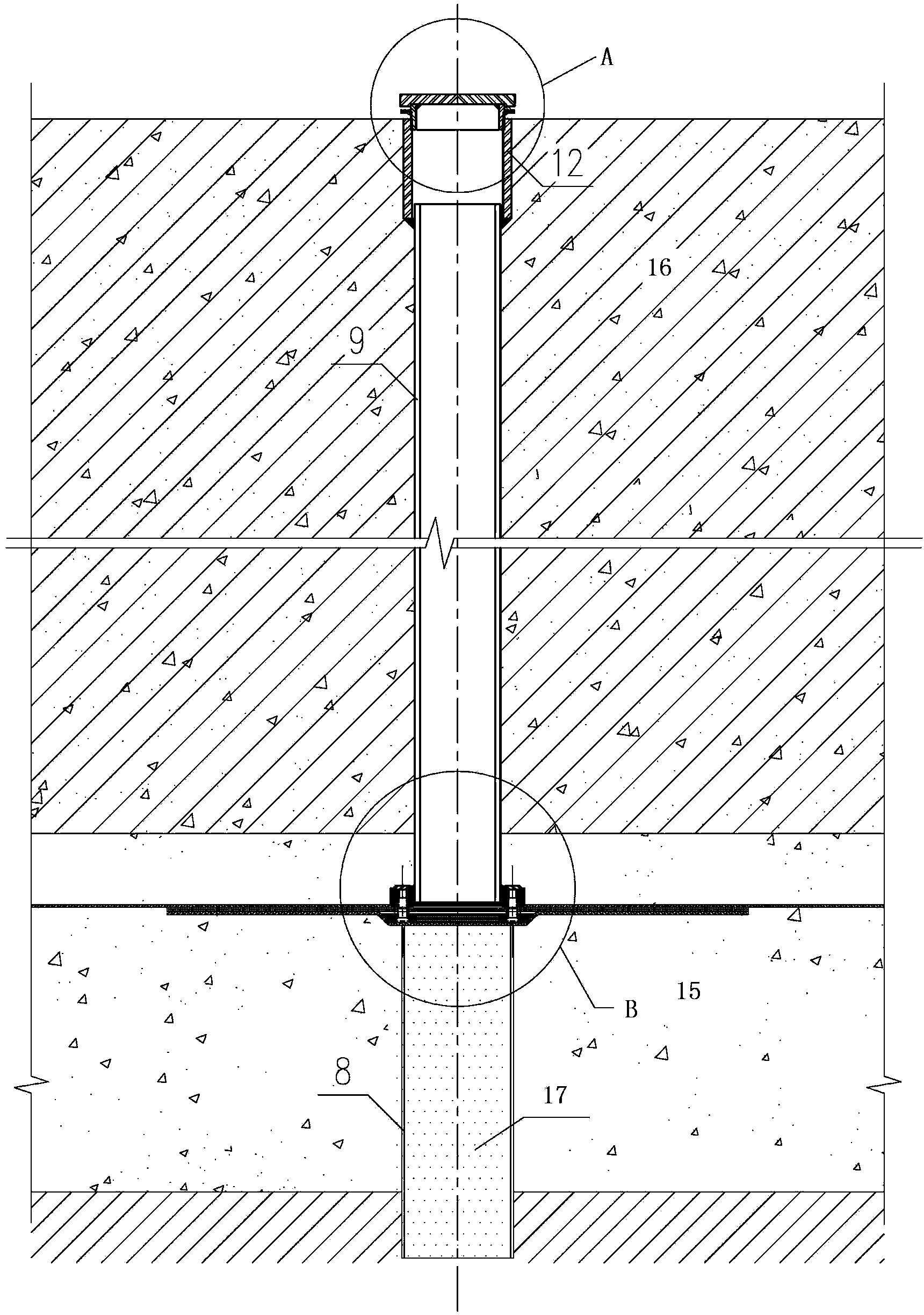
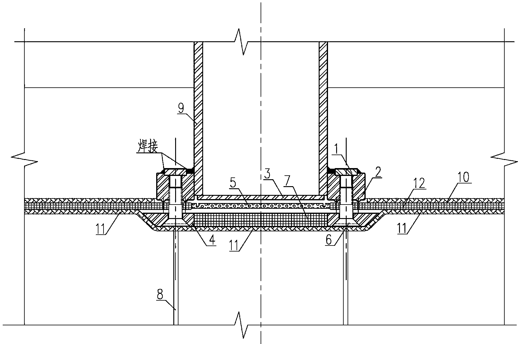
[0012] The present invention is a method for reserving grouting holes, the steps of which are as follows.

[0013] 1. Set the cushion grouting hole buried pipe 8 in the plain concrete cushion according to the specified position (the pipe can be made of PVC and other engineering plastic materials, and the pipe can be filled with cohesive soil 17 or other materials).

[0014] 2. Install the grouting hole buried pipe assembly on the upper part of the grouting hole buried pipe in the cushion layer. The buried pipe assembly is a supporting product of the factory-made components. The capping cover and the grouting hole bottom sealing device, the bottom plate grouting hole buried pipe is connected with the cushion layer grouting hole buried pipe through the grouting hole bottom sealing device, and the factory manufacturing and on-site assembly method steps are as follows.

...


PUM


Abstract

The invention discloses a method for embedment of a grouting hole in a base plate of an underground chamber. The method is characterized by comprising the following steps that (1) a cushion grouting hole embedded pipe is arranged in a concrete cushion of the underground chamber structure; (2) a base plate grouting hole embedded pipe assembly is arranged on the top of the cushion grouting hole embedded pipe, wherein the base plate grouting hole embedded pipe assembly comprises a base plate grouting hole embedded pipe, a grouting hole top sealing cover arranged on the top of the base plate grouting hole embedded pipe, and a grouting hole bottom sealing device arranged at the bottom of the base plate grouting hole embedded pipe; (3) a waterproof layer of the underground chamber is laid up, a plain concrete protective layer is poured, then rebars are bound, and base plate concrete is poured. The method for embedment of the grouting hole in the base plate of the underground chamber has the advantages that during the period of construction completion and operation of the underground chamber, concrete does not need to be removed in a gouging mode in the process of grouting, influence on the externally-wrapped waterproof layer is only caused within the range of the hole diameter of the grouting hole, a grouting pipe can easily, conveniently and directly enter into the soil mass below the base plate and the concrete cushion of the underground chamber, and grouting operation can be carried out.

Description

technical field [0001] The invention is applicable to the method of pre-embedding grouting holes in the floor of cast-in-situ reinforced concrete underground cavern structures (including tunnels, subway stations, etc.) by open-cut method. technical background [0002] After the underground cavern is completed, underground caverns such as shield tunnels, etc., which will be used for underground excavation at a close distance in the lower part, need to be considered to reserve grouting pipes on the floor of the underground cavern to prevent the later implementation of the underground cavern. Construction disturbs the surrounding soil layer and affects the foundation soil layer of the first underground cavern, which in turn affects the stability of the first built cavern. It is a method to ensure the stable and normal use of the first-built underground cavern by grouting the soil layer through the reserved grouting pipe on the bottom plate. [0003] When the original method en...

Claims


Application Information

Patent Timeline
Patent Type & Authority Applications(China)
IPC IPC(8): E02D3/12E02D31/00
Inventor 薛勇由广明
Owner SHANGHAI MUNICIPAL ENG DESIGN INST GRP
Why Eureka
Try Eureka