

Inner-oil-tube cleaning tool
A technology for oil pipes and knives, which is applied in the field of cleaning tools for cleaning stains in oil pipes. It can solve the problems of troublesome cleaning of oil pipes, incomplete cleaning, and high cost, and achieve the effects of long service life, low cost, and complete cleaning.
- Summary
- Abstract
- Description
- Claims
- Application Information
AI Technical Summary
Problems solved by technology
Method used
Image

Examples
Embodiment 1
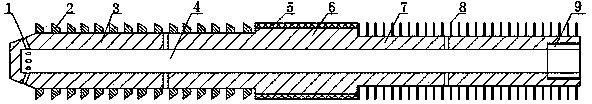
[0016] see figure 1 , the tool is cleaned in the oil pipe, and the cleaning knife includes three parts from left to right: a cutter body section 3, a grinding section 6 and a brush section 7, and a multi-ring ring-shaped scraper 2 is arranged on the outer peripheral surface of the cutter body section 3. A layer of polishing layer 5 is provided on the outer peripheral surface of the grinding section 6 , the outer surface of the brush section 7 is covered with a steel wire brush 8 , and the right end of the brush section 7 is also provided with an internal thread interface 9 .
[0017] When this embodiment is in use, the cutter body section 3 first extends into the oil pipe, and the internal thread interface 9 at the end of the brush section 7 is connected to the rotating device to drive the entire cleaning knife to rotate and push the cleaning knife into the oil pipe, and the cutter body section 3 is rotating When the scraper 2 on the surface scrapes and cuts the dirt on the in...
Embodiment 2
[0019] This embodiment is optimized as follows on the basis of Embodiment 1: the interior of the cutter body section 3, the grinding section 6 and the brush section 7 are all provided with connected water holes 4, and the front part of the cutter body section 3 , the middle part and the middle part of the brush section 7 are all provided with a water outlet hole 1 communicating with the water hole 4 and the external space.
[0020] The water hole 4 of this embodiment is used to pass through the decontaminated sewage, and the decontaminated sewage can moisten and soak the dirt on the inner wall of the pipe through the water outlet 1, which can increase the cleaning effect, make the cleaning more complete, and reduce the damage of the structure at the same time. The service life is extended, and the water outlet hole 1 is located at the front and middle of the cutter body section 3 and the middle of the brush section 7 so that the decontaminated sewage can be fully mixed with the...
Embodiment 3
[0023] This embodiment is further optimized on the basis of any of the above embodiments, specifically: the grinding layer 5 is a WC cemented carbide layer.
[0024] In this embodiment, WC cemented carbide has a series of excellent properties such as high hardness, wear resistance, good strength and toughness, heat resistance and corrosion resistance, especially its high hardness and wear resistance, so the grinding layer 5 adopts Made of WC cemented carbide not only can meet the working requirements of the downhole, but also has strong wear resistance, which greatly prolongs the service life of the grinding layer 5 .
[0025] Preferably, the thickness of the grinding layer 5 is 8-12 mm. While prolonging the service life of the grinding layer 5, the waste of materials is reduced, so the thickness of the grinding layer 5 is 8-12 mm, which can not only ensure the normal use of the grinding layer 5, but also reduce the waste of materials.
PUM
| Property | Measurement | Unit |
|---|---|---|
| Thickness | aaaaa | aaaaa |
Abstract
Description
Claims
Application Information