Gas engine air supply pipe interlocking valve mechanism

A gas engine and gas supply pipeline technology, applied to combustion engines, internal combustion piston engines, engine components, etc., can solve the problems of not having the function of manually closing the gas supply pipeline, potential safety hazards, and inability to discharge, so as to shorten the emergency response time , The effect of eliminating potential safety hazards

Active Publication Date: 2014-05-21
GUANGXI YUCHAI MASCH CO LTD
View PDF4 Cites 4 Cited by
  • Summary
  • Abstract
  • Description
  • Claims
  • Application Information

AI Technical Summary

Problems solved by technology

[0003] The defect of the existing gas engine gas supply pipeline system is that: the ECU controls the opening and closing of the solenoid valve. Once the solenoid valve fails, it does not have the function of manually closing the gas supply pipeline; after the engine stops, the pipeline between the gas supply system and the engine There is still gas remaining, which cannot be discharged, and there are potential safety hazards
In particular, the gas supply pipeline of many engines is relatively long (such as marine engines, the gas supply pipeline is generally connected from the deck of the ship to the engine compartment), and a large amount of gas remaining in the pipeline will cause a greater safety hazard

Method used


Image

  • Gas engine air supply pipe interlocking valve mechanism
  • Gas engine air supply pipe interlocking valve mechanism
  • Gas engine air supply pipe interlocking valve mechanism

Examples


Embodiment 1

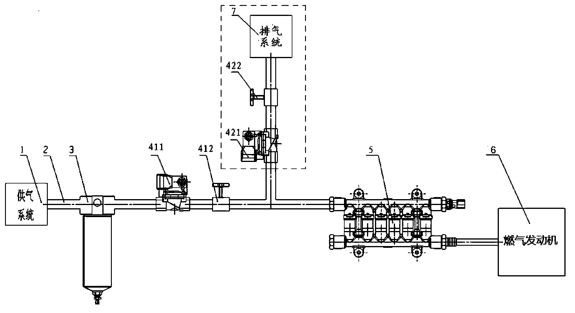
[0022] Such as figure 2 As shown, the gas engine air supply pipeline interlock valve mechanism in Embodiment 1 includes a first solenoid valve 411 and a second solenoid valve 421 controlled by the electronic control unit ECU, and a manually controllable first manual valve 412 and a second manual valve. Valve 422. The first solenoid valve 411 is arranged on the gas supply pipeline 2 between the gas filter 3 and the gas injection system 5 ; the first manual valve 412 is connected in series to the rear end pipeline of the first solenoid valve 411 . One end of the gas injection system 5 communicates with the rear end pipeline of the first manual valve 412 , and the other end of the gas injection system 5 communicates with the gas engine 6 . Exhaust lines (such as figure 2 The dotted line frame part) communicates with the pipeline between the first manual valve 412 and the gas injection system 5 . The exhaust pipeline is provided with a second solenoid valve 421 , a second man...

Embodiment 2

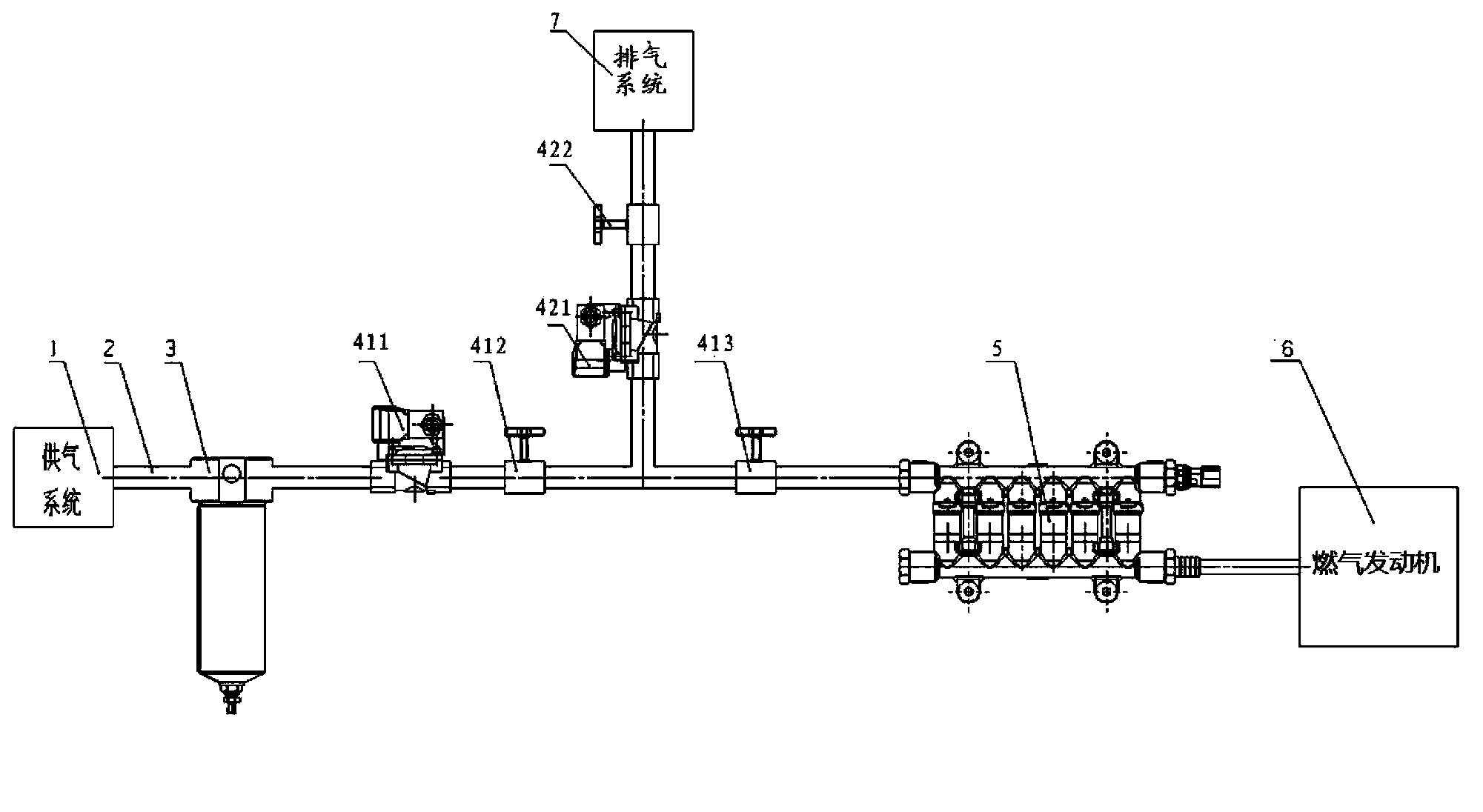
[0028] In practice, the air supply line of the engine is sometimes relatively long. In Embodiment 1, if the staff finds that the electromagnetic valve is faulty, it will take a long time to go to the vicinity of the gas supply system to manually close the first manual valve 412 near the engine. Therefore, a more preferred embodiment 2 is further proposed on the basis of embodiment 1. Such as image 3 As shown, the gas engine air supply pipeline interlock valve mechanism in Embodiment 2 includes a first solenoid valve 411 and a second solenoid valve 421 controlled by the electronic control unit ECU, and a manually controllable first manual valve 412 and a second manual valve. Moving valve 422 and the third manual valve 413. The first solenoid valve 411 is set on the gas supply pipeline 2 between the gas filter 3 and the gas injection system 5; the first manual valve 412 and the third manual valve 413 are sequentially connected to the rear end pipe of the first solenoid valve ...


PUM


Abstract

The invention discloses an interlocking valve mechanism. The interlocking valve mechanism is connected with a gas filter and a gas spraying system in an air supply pipe to control the air supply pipe to be opened and closed. The gas engine air supply pipe interlocking valve mechanism comprises a first electromagnetic valve, a first manual valve and a gas discharging pipe, the first electromagnetic valve is arranged between the gas filter and the gas spraying system in the air supply pipe, the first manual valve is arranged at the position, at the back end of the first electromagnetic valve, of the air supply pipe, the gas discharging pipe is communicated with the portion, between the gas filter and the gas spraying system, of the air supply pipe and used for controlling residual gas in the air supply pipe to discharge the residual gas, and a second electromagnetic valve and a second manual valve are sequentially arranged on the gas discharging pipe in the gas discharging direction. When the electromagnetic valves lose efficiency, the air supply pipe can be manually controlled through the interlocking valve mechanism; after an engine is stopped, the residual gas in the air supply pipe can be timely discharged out of the pipe, and potential safety hazards are eliminated.

Description

technical field [0001] The invention relates to a gas engine gas supply pipeline system, in particular to a gas engine gas supply pipeline interlock valve mechanism. Background technique [0002] The solenoid valve is used in the air supply pipeline system of the gas engine, and its opening and closing are controlled by the electronic control unit (ECU). At present, the existing gas engine gas supply pipeline system such as figure 1 shown. When the gas engine is working normally, the gas supply system 1' starts the gas supply, the solenoid valve 4' controlled by the ECU opens, the gas passes through the gas supply pipeline 2', is filtered by the gas filter 3' and is aligned with the gas injection system 5'. The flow and pressure control is supplied to the gas engine 6'; when the gas engine needs to be shut down, the gas supply system 1' closes the gas supply, the solenoid valve 4' controlled by the ECU is closed, and the supply to the gas engine 6' is stopped. [0003] Th...

Claims


Application Information

Patent Timeline
Patent Type & Authority Applications(China)
IPC IPC(8): F02M21/02
CPCY02T10/30
Inventor 潘俊韦文学李玉
Owner GUANGXI YUCHAI MASCH CO LTD
Why Eureka
Try Eureka