A hydraulic or pneumatic transmission device with a figure-eight structure

A transmission device and pneumatic transmission technology, applied in transmission devices, fluid pressure actuation devices, motor vehicles, etc., can solve problems such as complex structure, affecting the use effect of the cover plate, and inconsistent operation of the two cover plates, so as to achieve convenient operation , the effect of simple structure

Inactive Publication Date: 2016-06-08
NINGBO JIANGDONG CHENGCHUANG IND PROD DESIGN CO LTD +1
View PDF9 Cites 0 Cited by
  • Summary
  • Abstract
  • Description
  • Claims
  • Application Information

AI Technical Summary

Problems solved by technology

Therefore, the general rotating device is provided with two independent sprockets to work, not only the structure is complicated, but also the two cover plates often run inconsistently, which affects the actual use effect of the cover plate

Method used


Image

  • A hydraulic or pneumatic transmission device with a figure-eight structure
  • A hydraulic or pneumatic transmission device with a figure-eight structure
  • A hydraulic or pneumatic transmission device with a figure-eight structure

Examples


no. 1 example

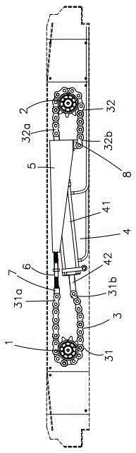
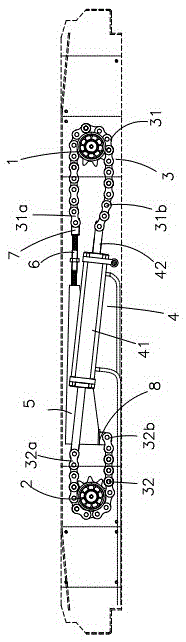
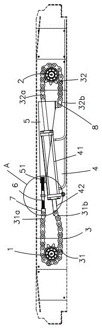
[0026] A hydraulic or pneumatic transmission device with a figure-eight structure of the present invention includes a first sprocket 1, a second sprocket 2 and a chain 3, wherein the chain 3 has the first sprocket 1 as one end and the second sprocket 2 is that the other end is cross-wound on the first sprocket 1 and the second sprocket 2 in a figure-eight structure. The chain 3 is connected with a chain driving device 4 capable of driving the chain 3 to move.

[0027] In the embodiment, the chain 3 includes a first side chain 31 and a second side chain 32. The first side chain 31 includes a first side chain upper end 31a and a first side chain lower end 31b. The first side chain 31 is wound around the middle. On the first sprocket 1, the upper end 31a of the first side chain and the lower end 31b of the first side chain both extend in the direction of the second side chain. The second side chain 32 includes the upper end 32a of the second side chain and the second side. The chain...

no. 2 example

[0038] In the embodiment, the chain driving device 4 is a pneumatic driving device, and the hydraulic driving device is an air cylinder. The undescribed parts are the same as the first embodiment.

[0039] In this embodiment, an air cylinder is used instead of the oil cylinder in the first embodiment, which is suitable for smaller vehicles. Compared with the oil cylinder drive, the air cylinder is more economical, has more types and is cleaner.

[0040] The invention has the advantages of simple structure, convenient operation, the chain is arranged on two sprockets in a figure of eight, and the two sprockets can rotate in opposite directions at the same time, so that the device connected with the sprockets can open and close together.


PUM


Abstract

The invention discloses a hydraulic or pneumatic transmission device with an 8-shaped structure. The hydraulic or pneumatic transmission device comprises a first chain wheel, a second chain wheel and a chain, wherein the chain is wound on the first chain wheel and the second chain wheel in a form of the 8-shaped structure, with the first chain wheel as one end and the second chain wheel as the other end; a chain driving device which can be used for driving the chain to move is connected to the chain. The first chain wheel and the second chain wheel are driven by the chain to reversely rotate at the same speed with respective wheel axles as axes; the rotating shafts of devices requiring to be simultaneously opened or closed are respectively fixed on the first chain wheel and the second chain wheel, and thus the devices can rotate in opposite directions, with the same angular velocity. A tightening screw is arranged between a first side chain and a second side chain and is used for adjusting the tightness of the side chains so as to ensure the stable operation of the whole driving device and prevent the falling and sliding of the side chains. The hydraulic or pneumatic transmission device disclosed by the invention has the advantages that the structure is simple; the operation is convenient; the chain is wound on the two chain wheels to be shaped like an 8, so that the two chain wheels can rotate in opposite directions and at the same time and the devices connected with the chain wheels can be opened or closed simultaneously.

Description

Technical field [0001] The invention relates to the field of mechanical transmission devices, in particular to a hydraulic or pneumatic transmission device with a figure-eight structure. Background technique [0002] With the development of economy, there are more and more road transportation vehicles, and all kinds of pollution caused by transportation vehicles during driving, especially the bare transportation muck without the roof of the car box, are caused by throwing, dusting and dripping. Sewage, etc. cause more serious road pollution. On the one hand, there is dust on the road, which affects the health of traffic and pedestrians. What is more, because of the pollution on the road, the high-speed truck tires roll over the pollutant particles on the road and generate high pressure instantly. Under pressure, it will explode in a short time and fission produces a large amount of fine dust, which spreads into the air. It can not fall back to the ground for a long time and pollu...

Claims


Application Information

Patent Timeline
Patent Type & Authority Patents(China)
IPC IPC(8): F16H7/06F15B15/02B60P7/02
CPCF16H7/06F16H2007/0812F16H2007/0842
Inventor 涂佳丽
Owner NINGBO JIANGDONG CHENGCHUANG IND PROD DESIGN CO LTD
Why Eureka
Try Eureka