
Spiral conveyor structure of sand mixer

A technology of sand mixer and sand mouth, which is applied in the cleaning/processing machinery of casting mold materials, casting molding equipment, metal processing equipment, etc., which can solve the problem of unfavorable working environment and workers' health, affecting the amount of resin, curing agent, etc. Affect the ultimate strength of resin sand and other issues, to achieve good practical performance, reduce maintenance rate, and improve strength

Active Publication Date: 2014-05-28
浙江红马铸造有限公司
View PDF8 Cites 0 Cited by
  • Summary
  • Abstract
  • Description
  • Claims
  • Application Information

AI Technical Summary

Problems solved by technology

[0002] The mixing cage stirs and mixes the molding sand. In the prior art, the molding sand is mixed in the mixing cage of the sand mixer, and the sand is directly discharged from the sand outlet to the tooling. The mixing process of the molding sand in the mixing cage produces more dust. , a large amount of dust is released after the sand is directly produced, which is not good for the working environment on site and the health of workers. The dust easily affects the amount of resin and curing agent added, and affects the final strength of the resin sand. The dust is effectively treated by the dust collector. When the dust When the concentration reaches a certain level, factors such as too low conveying temperature will easily affect the normal use of the dust collector, the reliability is poor, and the maintenance rate of the dust collector is high, which greatly increases the working intensity and production cost.

Method used


Image

  • Spiral conveyor structure of sand mixer

Examples


Embodiment Construction

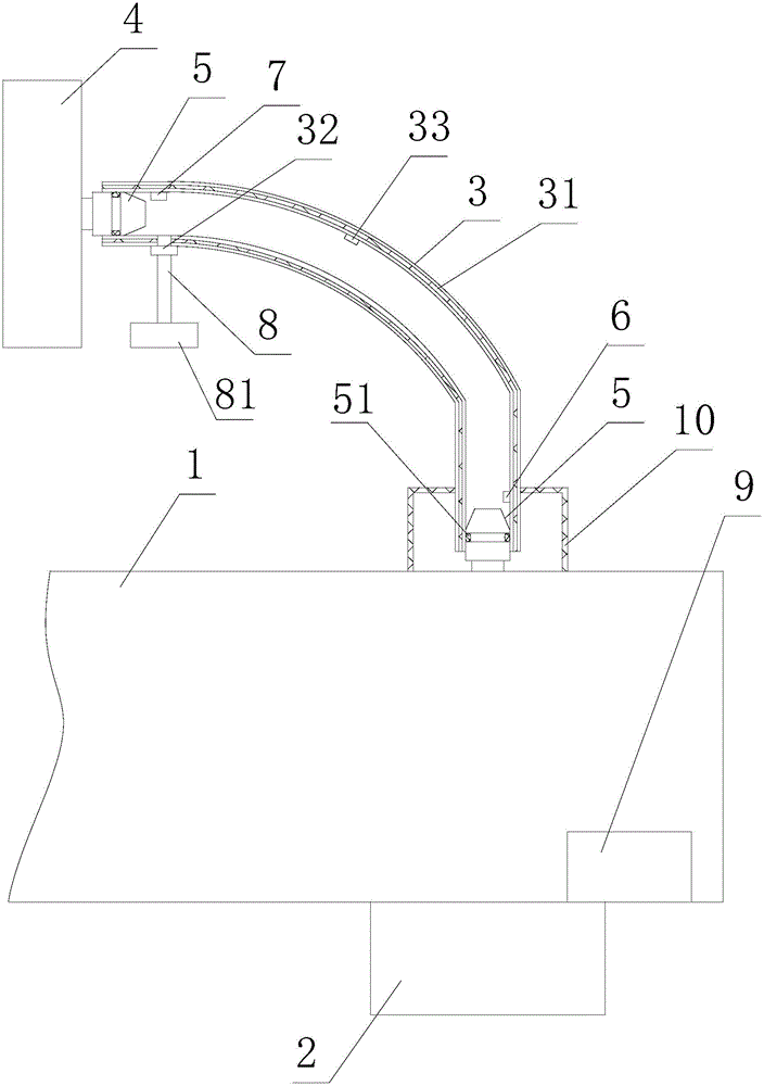
[0012] Such as figure 1 As shown: the cage structure of the sand mixer, including a body 1 with a sand outlet 2 at the end, the body is provided with a dust removal device adjacent to the sand outlet 2, and the dust removal device includes a connecting pipe connected to the body 1 at one end 3. The dust remover 4, the dust remover 4 is arranged at the other end of the connecting pipe 3, the body 1 and the dust remover 4 are provided with a connecting piece 5 for fixing the connecting pipe 3, the front of the connecting piece 5 The part is a round platform with a small outside and a big inside. The middle part of the connecting piece 5 is provided with a sealing ring 51. The rear part of the connecting piece 5 is provided with a threaded mounting part. The connecting pipe 3 is provided with a constant temperature layer 31. The feed port of the connecting pipe 3 is provided with a speed sensor 6 for detecting the air volume of the dust remover 4, and the discharge port of the co...


PUM

PropertyMeasurementUnit
Thicknessaaaaaaaaaa

Abstract

The invention relates to a spiral conveyor structure of a sand mixer. The spiral conveyor structure comprises a main body, wherein a sand outlet is arranged at the bottom end of the main body, a dust collection device is arranged on the main body at a part which is adjacent to the sand outlet, the dust collection device comprises a connecting pipe and a dust collector, a speed sensor is arranged at a feeding opening part of the connecting pipe, a temperature sensor is arranged at a discharging opening part of the connecting pipe, the speed sensor and the temperature sensor are respectively electrically connected with the dust collector, and the spiral conveyor structure further comprises a dust concentration detecting instrument. The spiral conveyor structure has the advantages that the concentration of dust which is produced at the sand outlet part is detected by the dust concentration detecting instrument so that the dust is effectively absorbed by the dust collector; dust treatment reliability can be ensured through the constant temperature treatment on a temperature in the connecting pipe by a constant temperature layer, the detection of the temperature in the connecting pipe by the temperature sensor and the detection of air volume which is generated by the dust collector by the speed sensor; great practical performance and simple operation are realized; the maintenance rate of the dust collector is reduced, the work intensity is lowered, and the production cost is lowered.

Description

technical field [0001] The invention relates to a mixing cage structure of a sand mixer. Background technique [0002] The mixing cage stirs and mixes the molding sand. In the prior art, the molding sand is mixed in the mixing cage of the sand mixer, and the sand is directly discharged from the sand outlet to the tooling. The mixing process of the molding sand in the mixing cage produces more dust. , a large amount of dust is released after the sand is directly produced, which is not good for the working environment on site and the health of workers. The dust easily affects the amount of resin and curing agent added, and affects the final strength of the resin sand. The dust is effectively treated by the dust collector. When the dust When the concentration reaches a certain level, factors such as too low conveying temperature will easily affect the normal use of the dust collector, the reliability is poor, and the maintenance rate of the dust collector is high, which greatly...

Claims


Application Information

Patent Timeline
IPC IPC(8): B22C5/04
Inventor 李伟峰
Owner 浙江红马铸造有限公司
Learn More