Workpiece scanning imaging method based on laser sensor and robot

A laser sensor, scanning imaging technology, applied in the direction of instruments, optical devices, measuring devices, etc., can solve problems such as performance interference, achieve flexible use, strong practicability, and solve the effects of insufficient anti-interference performance

Inactive Publication Date: 2014-05-28
SOUTH CHINA UNIV OF TECH
View PDF8 Cites 16 Cited by
  • Summary
  • Abstract
  • Description
  • Claims
  • Application Information

AI Technical Summary

Problems solved by technology

In some special industrial environments, such as strong arc light, dust, smoke and other adverse interference factors in the welding site, the performance of traditional CCD cameras has been seriously disturbed, and traditional CCD cameras cannot perform well in this environment. to complete the task

Method used


Image

  • Workpiece scanning imaging method based on laser sensor and robot
  • Workpiece scanning imaging method based on laser sensor and robot
  • Workpiece scanning imaging method based on laser sensor and robot

Examples


Embodiment

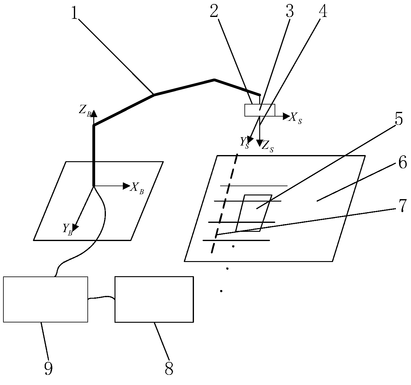
[0038] A striped laser sensor is installed at the end of the robot. The sensor and the robot (including the robot controller) are fixedly installed on the end flange of the robot to jointly complete the measurement task of obtaining the contour point data of the workpiece obtained by laser scanning. .

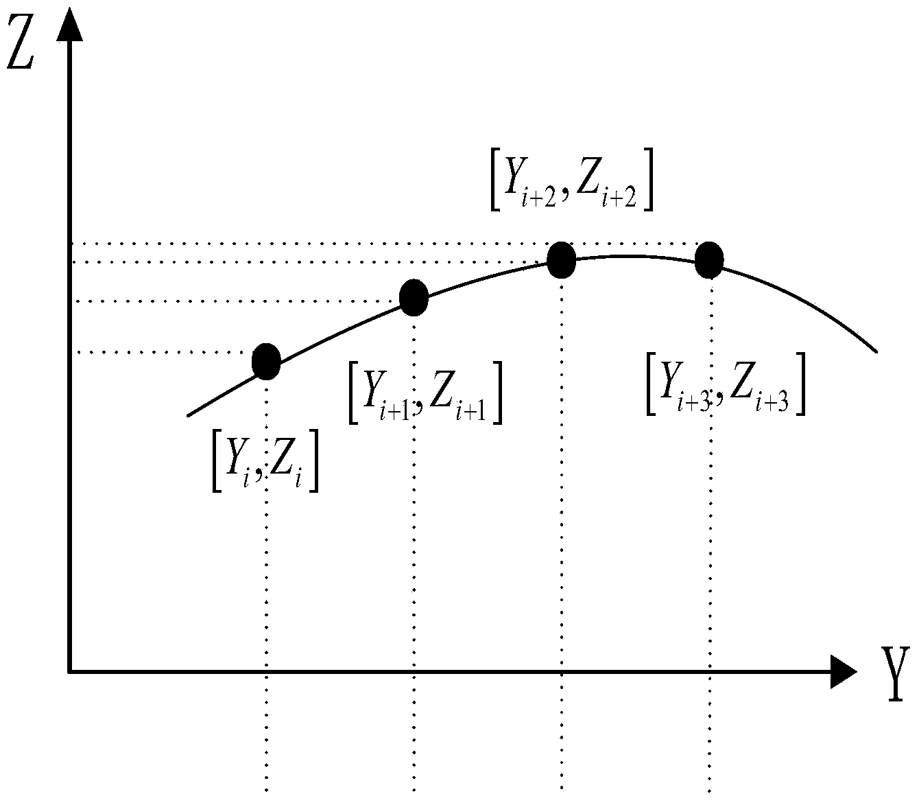
[0039] When the laser beam emitted by the stripe laser sensor used in this method is projected on the surface of the object to be measured, the laser beam will form an image consistent with the surface contour of the object to be measured. On the laser beam, there are a series of continuous and uniform P Laser sampling points, and then the sensor returns the P sampling points in the laser beam relative to the Z-axis and X-axis coordinate values ​​in the sensor measurement coordinate system.

[0040] The computer communicates with the laser sensor and the robot controller to complete the task of collecting and processing laser scanning point data and then imaging the contour of the w...


PUM


Abstract

The invention provides a workpiece scanning imaging method based on a laser sensor and a robot. The method includes the following steps of (A) obtaining workpiece profile point data obtained through laser scanning, and (B) processing the point data so as to generate a workpiece profile image, wherein by means of the step of obtaining the workpiece profile point data obtained through laser scanning, the function of obtaining the laser scanning point data is achieved; by means of the step of processing the point data to generate the workpiece profile image, the problem of obtaining a workpiece profile binaryzation image through the original laser scanning point data is solved. The method has the advantages of being practical, flexible, good in anti-interference performance and the like and solving the problem that a traditional CCD camera is insufficient in anti-interference performance in a special industrial operation situation.

Description

Technical field [0001] The invention relates to a workpiece scanning imaging technology, in particular to a workpiece scanning imaging method based on sensors and robots; the scanning imaging method of the invention is a workpiece scanning imaging method based on stripe laser sensors and industrial robots. Robots are mechanical motion execution devices, industrial robots and stripe laser sensors are used as measuring devices, and computers are used as communication, data acquisition and processing platforms to scan and image workpieces. Background technique [0002] Because the vision system has good detection performance and positioning performance, the development of robot vision system has become a hot spot and focus in the field of robot research. The visual sensing method has received more and more attention due to its rich information, high sensitivity, high precision, and no contact with the workpiece. [0003] At present, the images collected by vision sensors include imag...

Claims


Application Information

Patent Timeline
Patent Type & Authority Applications(China)
IPC IPC(8): G01B11/245
Inventor 张铁李波邹焱飚
Owner SOUTH CHINA UNIV OF TECH
Why Eureka
Try Eureka