Underwater positioning and navigation system and method based on DGPS

An underwater positioning and navigation system technology, applied in satellite radio beacon positioning systems, radio wave measurement systems, measurement devices, etc., can solve problems such as large components, the inability to increase the number of underwater positioning and navigation receivers, and unfavorable concealment. , to achieve an unlimited number of effects

Active Publication Date: 2014-05-28
SHANGHAI JIAO TONG UNIV
View PDF9 Cites 32 Cited by
  • Summary
  • Abstract
  • Description
  • Claims
  • Application Information

AI Technical Summary

Problems solved by technology

The disadvantages are: 1. The underwater transponder needs to transmit acoustic signals to the outside world, which increases power consumption and has poor concealment
2. Due to the need for two-way sending and receiving signals, the number of underwater transponders is limited by the processing capacity of buoys and cannot be increased indefinitely
This method has the following limitations: 1. The required components of the system are huge, requiring at least 5 buoys (buoys), data centers, sea surface wireless communication links, and underwater wireless communication links
2. Underwater navigation receiver and buoy need two-way communication
Underwater positioning and navigation receivers need to emit underwater acoustic signals, which consumes a lot of power and is not conducive to concealment
3. The number of underwater positioning and navigation receivers cannot be increased infinitely
4. The underwater navigation receiver cannot directly obtain its own position
Increases time required for positioning, reduces reliability

Method used


Image

  • Underwater positioning and navigation system and method based on DGPS
  • Underwater positioning and navigation system and method based on DGPS
  • Underwater positioning and navigation system and method based on DGPS

Examples


Embodiment Construction

[0031] The present invention will be described in detail below in conjunction with specific embodiments. The following examples will help those skilled in the art to further understand the present invention, but do not limit the present invention in any form. It should be noted that those skilled in the art can make several modifications and improvements without departing from the concept of the present invention. These all belong to the protection scope of the present invention.

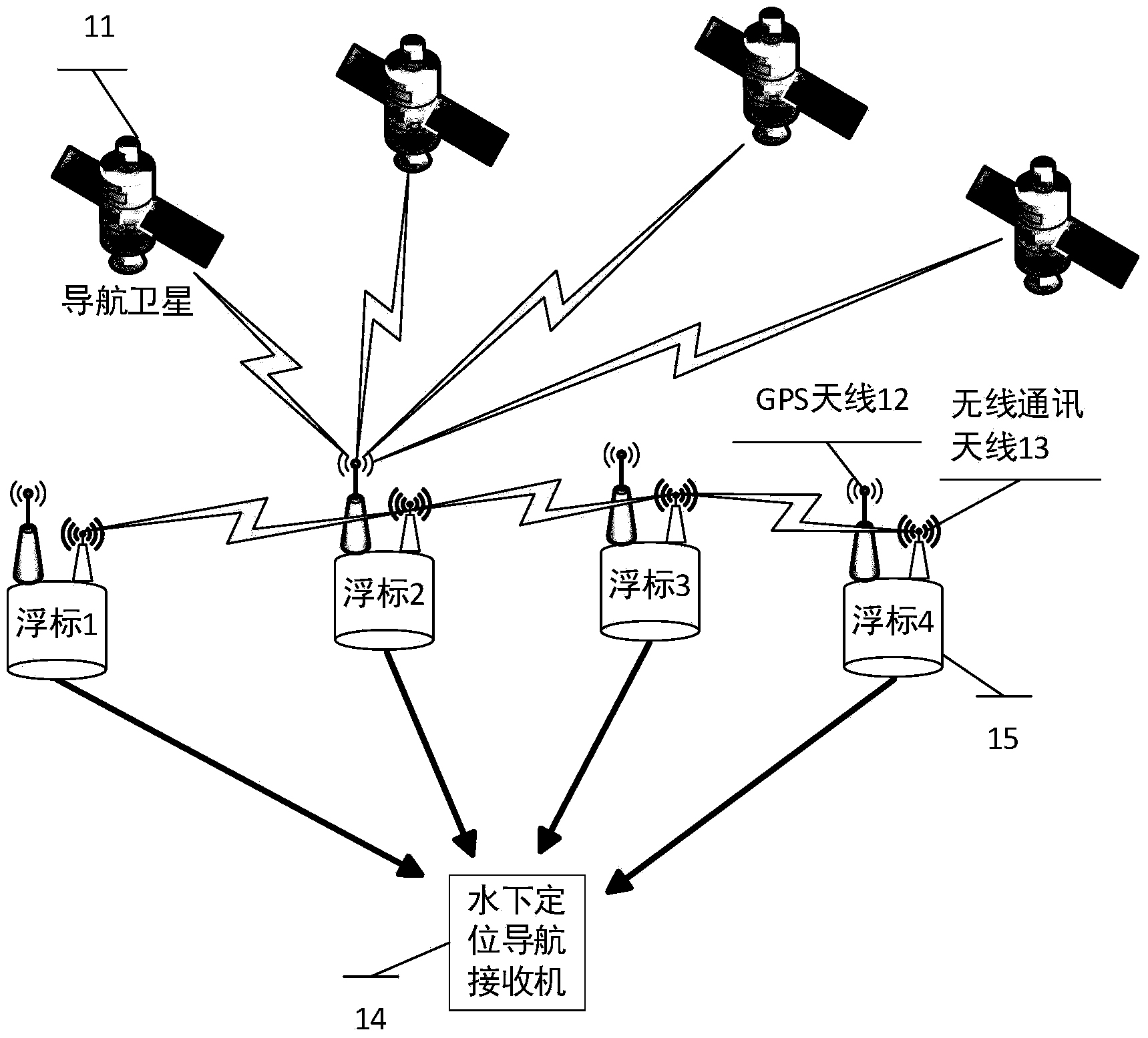
[0032] Such as figure 1 As shown, it is a block diagram of a positioning and navigation system according to an embodiment of the present invention, which is composed of GNSS satellites 11 , four DGPS buoys 15 and one underwater positioning and navigation receiver 14 . The DGPS buoy (hereinafter referred to as the buoy) receives GNSS navigation signals through the GPS antenna 12 to realize positioning in the earth coordinate system. At the same time, the buoys communicate with each other through t...


PUM


Abstract

The invention discloses an underwater positioning and navigation system and method based on the DGPS. The system is composed of GNSS satellites, at least four DGPS buoys and at least one underwater positioning and navigation receiver. The buoys receive GPS signals and are in wireless communication with one another so that DGPS positioning can be achieved. The buoys broadcast navigation signals to water. Frequency spread can be conducted on the navigation signals through pseudorandom frequency spread codes, wherein the frequency spread codes play a role of ranging codes at the same time. The underwater positioning and navigation receivers do not need to transmit signals outwards. The underwater positioning and navigation receivers resolve the positions of the underwater positioning and navigation receivers in the earth coordinates and the accurate positions of the underwater positioning and navigation receivers relative to a base station by means of the received navigation signals of the buoys. Time synchronization of the underwater positioning and navigation receivers and the UTC is achieved. Multiple underwater positioning and navigation receivers can be arranged in the system to simultaneously receive the navigation signals, and the number of the underwater positioning and navigation receivers is not limited. The underwater positioning and navigation system and method can be applied to the underwater exploration field, the under water construction field, the underwater security and protection field, the underwater navigation field and other fields.

Description

technical field [0001] The invention relates to the field of underwater positioning and navigation, in particular to positioning and navigation and time synchronization technology under the condition of hidden underwater targets. Background technique [0002] Underwater navigation positioning Navigation technology has very important application value in the fields of marine monitoring, marine exploration, marine rights protection, underwater archaeology, underwater construction, underwater security and military. Acoustic-based underwater positioning and navigation systems are mainly divided into two categories according to the propagation path of underwater acoustic signals: two-way mode and one-way mode. [0003] The two-way mode is also called the answer mode, which requires the underwater positioning equipment to be equipped with a transponder. Two-way sending and receiving underwater acoustic signals between the buoy and the transponder realizes positioning. Most of th...

Claims


Application Information

Patent Timeline
Patent Type & Authority Applications(China)
IPC IPC(8): G01S19/42
CPCG01S19/10G01S19/25G01S19/46
Inventor 关新平赵健康王红雨贺超峰
Owner SHANGHAI JIAO TONG UNIV
Why Eureka
Try Eureka