Iron nitride permanent magnet and technique for forming iron nitride permanent magnet

A technology of permanent magnets and iron crystals, applied in the field of permanent magnets and used to form permanent magnets, can solve the problems of high production costs of permanent magnets, shortage of supply of rare earth elements, price rise, etc.

Active Publication Date: 2014-05-28
RGT UNIV OF MINNESOTA
View PDF6 Cites 20 Cited by
  • Summary
  • Abstract
  • Description
  • Claims
  • Application Information

AI Technical Summary

Benefits of technology

This patented technology allows for better control over how data flows through an electronic device compared with previous methods that had been previously used before it was developed.

Problems solved by technology

The technical problem addressed by this patented technology relates to finding ways to make more affordable magnetic materials while also reducing their cost compared with traditional methods like mineral processing.

Method used


Image

  • Iron nitride permanent magnet and technique for forming iron nitride permanent magnet
  • Iron nitride permanent magnet and technique for forming iron nitride permanent magnet
  • Iron nitride permanent magnet and technique for forming iron nitride permanent magnet

Examples


Embodiment

[0067] A series of experiments were performed to evaluate one or more aspects of the example iron nitrides described herein. Specifically, various example iron nitride materials were formed via urea diffusion and subsequently evaluated. The weight ratio of urea to bulk iron was varied to determine the dependence of the structure of the iron nitride material on this ratio. Such as Figure 12 As shown in , five different examples were formed using urea to iron weight ratios of about 0.5 (ie, 1:2), 1.0, 1.2, 1.6, and 2.0.

[0068] For reference, at temperatures above about 1573°C, the main chemical reaction process for the urea diffusion process is:

[0069] CO(NH 2 ) 2 →NH 3 +HNCO (1)

[0070] HNCO+H 2 O→2NH 3 +CO 2 (2)

[0071] 2NH 3 →2N+3H 2 (3)

[0072] 2N→N 2 (4)

[0073] During this reaction, nitrogen atoms can be relatively easily recombined into molecules, as shown in equation (4). Thus, in some embodiments, recombination of nitrogen atoms may be reduce...


PUM

PropertyMeasurementUnit
Diameteraaaaaaaaaa
Diameteraaaaaaaaaa
Thicknessaaaaaaaaaa

Abstract

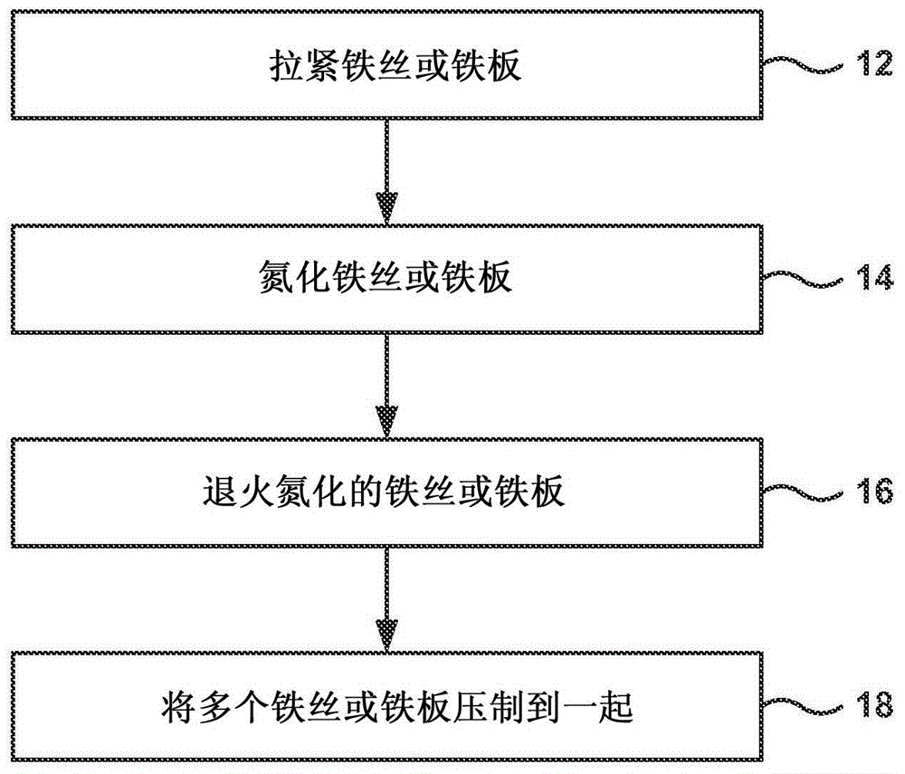
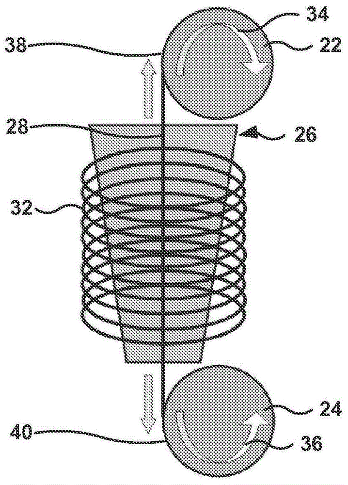
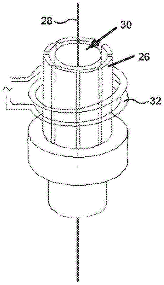
A permanent magnet may include a Fe16N2 phase constitution. In some examples, the permanent magnet may be formed by a technique that includes straining an iron wire or sheet comprising at least one iron crystal in a direction substantially parallel to a <001>; crystal axis of the iron crystal; nitridizing the iron wire or sheet to form a nitridized iron wire or sheet; annealing the nitridized iron wire or sheet to form a Fe16N2 phase constitution in at least a portion of the nitridized iron wire or sheet; and pressing the nitridized iron wires and sheets to form bulk permanent magnet.

Description


Claims


Application Information

Patent Timeline
Owner RGT UNIV OF MINNESOTA
Why Eureka
Try Eureka