H-shaped steel worm and worm gear linkage clamping device

A worm gear and clamping device technology, applied in auxiliary devices, auxiliary welding equipment, welding/cutting auxiliary equipment, etc., can solve the problems of complicated operation process, large space occupation ratio, and large device volume, etc., and achieves simple and scientific structure. The effect of improving production efficiency, ensuring clamping accuracy and machining quality

Inactive Publication Date: 2014-06-04
HUBEI HONGYI STEEL CONSTR ENG
View PDF0 Cites 5 Cited by
  • Summary
  • Abstract
  • Description
  • Claims
  • Application Information

AI Technical Summary

Problems solved by technology

[0002] At present, the clamping device for H-shaped steel components uses more air cylinders and hydraulic cylinders as power to clamp the H-shaped steel workpiece, and each driving device is paired with a push arm to push the workpiece. Due to the large span of the workpiece, both sides The driving and clamping devices arranged independently cannot ensure a good clamping balance of the workpiece during the clamping and centering process, which affects the welding quality of the H-shaped steel workpiece, and the operation process is complicated, and the adjustment process takes a long time. The device is bulky and occupies a large proportion of space, which affects the normal operation of the production line to a certain extent. At the same time, the failure probability of the complex drive device is high, and the maintenance cost of the equipment is high. Therefore, it is necessary to seek a clamping device with simple structure, simple operation, good performance and low cost. to meet the demand

Method used


Image

  • H-shaped steel worm and worm gear linkage clamping device

Examples


specific Embodiment approach

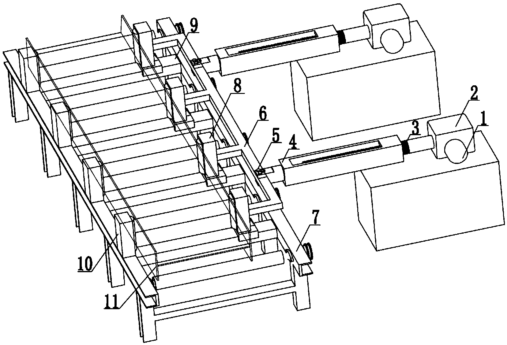
[0012] The present invention consists of a power drive device, a roller frame, and a clamping device. The clamping device is composed of a fixed clamping roller shaft and a movable clamping roller mechanism. The fixed clamping roller 10 corresponds to the distance between the rollers of the roller frame 7. The vacancy is fixedly installed on one side of the roller table frame 7; a slide rail 9 is provided in the space between the roller table of the roller table frame 7, and the linkage clamping roller shaft is connected by the roller shaft 8 and the connecting rod 6, and the linkage clamping roller shaft The roller shafts 8 and the slide rails 9 are slidably embedded in one-to-one correspondence, and are arranged on the other side of the roller frame relative to the fixed clamping roller shaft 10; the power drive device is composed of a motor 1, a worm gear reducer 2, a screw 3. The internal thread sleeve 4 is composed of two sets of power driving devices symmetrically arrange...


PUM


Abstract

The invention discloses an H-shaped steel worm and worm gear linkage clamping device and belongs to the field of machine manufacturing tools. The clamping device is composed of fixed clamping roll shafts and a movable clamping roll shaft mechanism. The movable clamping roll shaft mechanism is composed of power drive devices, linkage clamping roll shafts and sliding rails. The linkage clamping roll shafts are formed by integrally connecting roll shaft bodies with a connecting rod. All the roll shaft bodies of the linkage clamping roll shafts are connected with the sliding rails in a one-to-one correspondence and sliding fit mode and are opposite to the fixed clamping roll shafts and arranged on the other side of a roll bed rack. Telescopic arm ends of the two drive devices are symmetrically and perpendicularly connected with the connecting rod of the linkage clamping roll shafts. The linkage clamping roll shafts are driven by the two drive devices to slide along the sliding rails relative to the fixed clamping roll shafts to clamp H-shaped steel on the roll bed rack. According to the clamping device, single-side power drive is adopted to drive the linkage clamping roll shafts to move synchronously so as to achieve linkage clamping of H-shaped steel members, the clamping accuracy and machining quality of the H-shaped steel members at corresponding working positions are guaranteed, and production efficiency is effectively improved.

Description

technical field [0001] The invention discloses an H-shaped steel worm-gear linkage clamping device, which belongs to the field of machinery manufacturing tooling equipment. Background technique [0002] At present, the clamping device for H-shaped steel components uses more air cylinders and hydraulic cylinders as power to clamp the H-shaped steel workpiece, and each driving device is paired with a push arm to push the workpiece. Due to the large span of the workpiece, both sides The driving and clamping devices arranged independently cannot ensure a good clamping balance of the workpiece during the clamping and centering process, which affects the welding quality of the H-shaped steel workpiece, and the operation process is complicated, and the adjustment process takes a long time. The device is bulky and occupies a large proportion of space, which affects the normal operation of the production line to a certain extent. At the same time, the failure probability of the compl...

Claims


Application Information

Patent Timeline
Patent Type & Authority Applications(China)
IPC IPC(8): B23K37/04
CPCB23K37/0435
Inventor 周鹏张军魏巍王佳庆
Owner HUBEI HONGYI STEEL CONSTR ENG
Why Eureka
Try Eureka